
Open-source metal 3-D printer

| Type | |
|---|---|
| Authors | Gerald C. Anzalone Chenlong Zhang Bas Wijnen Paul G. Sanders Joshua M. Pearce |
| Location | Michigan, USA |
| Status | Designed Modelled Prototyped Verified |
| Verified by | MOST |
| Years | |
| Cost | USD 1,194.13 |
| Hardware license | CERN-OHL-S |
|---|---|
| Certifications | Start OSHWA certification |


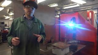
Technical progress in the open-source self replicating rapid prototyper (RepRap) community has enabled a distributed form of additive manufacturing to expand rapidly using polymer-based materials. However, the lack of an open-source metal alternative and the high capital costs and slow throughput of proprietary commercialized metal 3-D printers has severely restricted their deployment. The applications of commercialized metal 3-D printers are limited to only rapid prototyping and expensive finished products. This severely restricts the access of the technology for small and medium enterprises, the developing world and for use in laboratories. This paper reports on the development of a <$2000 open-source metal 3-D printer. The metal 3-D printer is controlled with an open-source micro-controller and is a combination of a low-cost commercial gas-metal MIG welder and a derivative of the Rostock, a deltabot RepRap. The bill of materials, electrical and mechanical design schematics, and basic construction and operating procedures are provided. A preliminary technical analysis of the properties of the 3-D printer and the resultant steel products are performed. The results of printing customized functional metal parts are discussed and conclusions are drawn about the potential for the technology and the future work necessary for the mass distribution of this technology.
For the latest MOST metal RepRap 3D printer see this
New software: Slicer and process improvements for open-source GMAW-based metal 3-D printing
Bill of Materials
[edit | edit source]| Item | Number | Cost(USD) | Source |
|---|---|---|---|
| All 12 Printed Parts @ $40/kg | $12.00 | Local RepRap | |
| All Fasteners | $2.00 | http://www.mcmaster.com/ | |
| M3 nut | 90 | ||
| M3x10 mm screw | 12 | ||
| M3x12mm screw | 48 | ||
| M3x20mm screw | 12 | ||
| M3x8mm set screw | 6 | ||
| M3washer | 102 | ||
| M8nut | 6 | ||
| M8set screw | 3 | ||
| 152mm x 152mm ceramic insulation | 1 | $ 4.00 | |
| Rods,bearings and ties | http://www.amazon.com/ | ||
| 300mm x 8mm smooth rod | 6 | $25.00 | |
| 304.8mm carbon fiber rod | 6 | $6.00 | |
| 608zz bearings | 6 | $2.40 | |
| LM8UUbearings | 6 | $6.00 | |
| Small wire ties | 3 | $0.50 | |
| Tie rod end | 24 | $ 8.00 | |
| 600mm T5 belt | 3 | $ 5.90 | http://www.polytechdesign.com/ |
| 241mm x 51mm x 4mm Aluminum plate | 3 | $114.00 | Local machine shop |
| NEMA17 Stepper motor (1.8 deg.,5.5kg-cm holding torque, 750mm wire) | 3 | $39.00 | http://www.kysanelectronics.com/ |
| Mechanical limit switch | 3 | $3.33 | http://www.digikey.com/ |
| Melzi Microcontroller board | 1 | $120.00 | http://web.archive.org/web/20160304170259/http://matterfy.com/ |
| Millermatic 140 Auto-set MIG Welder with Cart | 1 | $836.00 | http://www.millerwelds.com/ |
| Power supply | 1 | $8.00 | (Recycled)/Internet |
| Wires | 1 | $ 2.00 | (Recycled)/Internet |
| Total | $1,194.13 |
Printed Parts
[edit | edit source]
Print these STL files on any flavor of RepRap. The red parts in the image on the right are the printed parts. The SCAD if you need it.
- 3X File:End motor.stl
- 3X File:End idler.stl
- 3X File:Belt terminators.stl
- 3X File:MOST 12 tooth pulley.stl
- File:Effector.stl
- File:Carriage.stl
- File:Bed adapter.stl
Construction
[edit | edit source]Note to Makers
[edit | edit source]If you have made a RepRap before this will be easy -- if you are not familiar with RepRaps or Deltabots like the Rostock - more detailed build instructions are available at the MOST Prusa RepRap build page and the Delta Build Overview:MOST. Those links will give details on how, for example, you can braid the wires or configure the Melzi/Arduino microcontroller. This concept, however, is not limited to this specific design and should of course work for most RepRap printers -- you just need the fire proofing and your own welder...good luck! If you get it to work - please drop us a line.
Initial Prep
[edit | edit source]- Prepare all the materials listed in BOM
- Print all plastic components on a RepRap
- Ream the M3 screw holes in each plastic part and clean out nut traps with a sharp knife, make it fit for all M3 screws and nuts
Single pillar build
[edit | edit source]


- Attach the motor and the base plastic with M3 X 10mm screws with washers. Insert two M3 nuts into the set screw nut traps in the pulley, loosely insert two M3 X 8mm set screws into the pulley. Push the pulley through the motor rods and fasten all screws.
- Attach the limit switch to its holder on the base plastic using M2 X 10mm screws. Add some epoxy to make sure the switch doesn't move. Ensure that the screw in the carriage engages the switch arm. Adjust this screw to set the position where the carriage engages the limit switch.
- Use drill or knife to clean the rod openings, insert 2 parallel 300mm smooth rods into the holes in base plastic, use M3 X 12mm screw with washers to fasten all the rod to immobilize the both rods.
- Emerge the LM8UU bearings into oil for lubrication, insert 2 LM8UU bearings into the slots in the plastic shuttle, and firmly tighten each bearing with two small wire ties. Slide the LM8UU bearings with the plastic shuttles onto each rods.
- Fasten the top end of the parallel rods into the top plastics with M3 X 12mm screws with washers. Use the M8 set screw and M8 nut to fix two 608zz bearings into the center holes in the top plastic.
- Pass one end of the T5 belt through and around one belt terminator and pull the tail of the belt through other terminator. Loop the end of the belt around the pulley. Loop the other end of the belt around the 608zz bearings. Attach one terminator to the plastic shuttle with LM8UU bearings with an M3 X 10mm screw with washer. Firmly fasten the terminators with a small wire tie.
3X
[edit | edit source]This ends the single pillar build. 3 pillars should be built in parallel. 241mm X 51mm aluminum plates are attached to both bottom and top plastics to make the frame a triangular prism shape.
Platform build
[edit | edit source]- Epoxy the tie wire ends to carbon fiber rods in both ends. M3 X 12mm screw and nut set is used to fasten the tie wire ends to the plastic shuttles. The other end is fastened to the plastic stage holder.
- Ensure the M3 screws are loosely thread through the hole in the tie wire ends so that it allows each carbon fiber arm to shift in all direction freely.
- 3 5cm long nails are thread into the plastic platform holder for supporting the 152mm X 152mm ceramic tray.
Electronics
[edit | edit source]
- For the wiring diagram see Fig. 2
- Step motors and limit switches are wired to corresponding terminals on the microcontroller board, which is connected to Linux computer with a USB cable.
- The board is powered with a recycled computer power supply.
- To control the welder we use one of these relays attached to the RAMPS auxiliary i/o and power pins. Changing the state of the pins to which the board is attached changes the state of the relay assigned to the activated pin. The relay contacts are then wired in parallel with the trigger switch in the handle of the welding gun. Toggling the handle trigger or the relay will toggle the welder. This way the welder can still be used as it normally would when not attached to the printer...
Safety
[edit | edit source]- Safety equipment is based off of standard MIG welding safety protocols
Work Area
[edit | edit source]- Use your metal 3D printer on a flat surface isolated from water and flammable materials.
- Verify that you have proper grounding with a metal on metal connection to your substrate.
- Ensure your gas cylinder is secured to an upright support or cart at all times and only use gas hoses designed for welding.
- Eliminate clutter from the work area as you will be raining sparks everywhere. Minimize the number of cables underfoot to avoid tripping.
- Examine hoses regularly for leaks, wear and loose connections and replace faulty lines. Spray with a soap and water mixture. Bubbles will show leaks.
- Ensure proper ventilation of work area. Welding fumes are hazardous. In a home garage leave a door or window open and run a box fan as an exhaust to remove fumes from your breathing area. We have also used masks.
Safety gear
[edit | edit source]- Wear safety glasses at all times while in the lab.
- When printing and/looking at the printer while printing wear a welders mask/welding helmet (auto-darkening or flip-shade with current ANSI certification) or look at it using a webcam. Do not watch the printer with unprotected eyes!
- Use pliers to pick up the substrate after printing or thick leather gloves
- Always wear flame-resistant lab coat and heavy duty leather gloves when handling the printed parts
- Wear leather shoes - high-tops (steel-toes are a bonus).
Metal 3D printing exposes you to welding for longer periods of time than is normal for routine welding. You should ensure that all of your skin is covered by something to avoid "sun burns".
Operation
[edit | edit source]The stage is controlled like a regular RepRap Delta 3-D printer. For a primer on the nomenclature try this. Download Repetier firmware and host software, use Arduino to upload the firmware to the stage, and set up Cura on the host. This will work on any type of computer but we recommend the free and open source Debian. Models can be created and modified with any 3-D editor, such as OpenSCAD, Blender or a CAD application like FreeCAD (for a more detailed list of free open source CAD programs go here. The model should be exported as an STL file. That is loaded into Cura and sliced to a toolpath. It may take a few tries to get all the settings right. The GCode is saved to disk and opened with Repetier Host, which sends it to the stage. When the platform reaches the welding gun, switch on the welder by plugging in cable leading to the switch (which is to be held pressed with a wire tie). While the print is going, pay attention to the distance between the gun and the object. This should start out at approximately 7 mm and remain the same. If it increases, either decrease the layer height, or slow down the movement (this can be done during the print with Repetier Host). If it decreases, do the opposite.
Experimental features
[edit | edit source]While the whole setup is still highly experimental, some parts are more experimental than others. Some features are listed here that are being tested with various levels of success. Cura will attempt to adjust the "line width" of the deposited filament by changing its feedrate. Currently the welder does not support any such adjustment, so some parts get more material than they should, while others get less. To solve this, a plugin for Cura was developed which converts these feedrate changes into nozzle speed changes. The plugin can be found with the scad file on github. This plugin also supports adding in custom commands when travel ends or starts. This can be used to activate a relay for switching the welder power.
See also
[edit | edit source]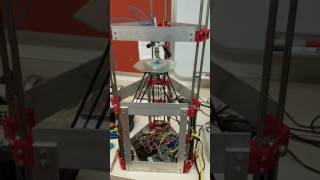
- Open Source Arc Analyzer: Multi-Sensor Monitoring of Wire Arc Additive Manufacturing
- Substrate Release Mechanisms for Gas Metal Arc Weld 3D Aluminum Metal Printing - how to get your print off the substrate with a hammer
- Low-cost Open-Source Voltage and Current Monitor for Gas Metal Arc Weld 3-D Printing
- Particle Swarm Optimization of Printing Parameters for Open-Source TIG-Based Metal 3D Printing
- Hypoeutectic Aluminum–Silicon Alloy Development for GMAW-Based 3-D Printing Using Wedge Castings
- Open-source Lab
- Open source 3-D printing of OSAT
- Life-cycle economic analysis of distributed manufacturing with open-source 3-D printers
- Environmental impacts of distributed manufacturing from 3-D printing of polymer components and products
- Building research equipment with free, open-source hardware
- Delft University of Technology - MIG+ Prusa I3
- Weld 3D - 1st commercial spin off
- see literature on "wire arc additive manufacturing" (WAAM)
- Mini Metal Maker- 3D printer designed specifically for metal clay which is then fired - $25 build instructions so quasi open source
- Código abierto Impresora 3-D para Metales
- Applications of Open Source GMAW-Based Metal 3-D Printing
- MOST open-source metal 3-D printer v2
- 3D Metal Printing Slicer Plugin
- In Situ Formation of Substrate Release Mechanisms for Gas Metal Arc Weld Metal 3-D Printing
- Low-cost Open-Source Voltage and Current Monitor for Gas Metal Arc Weld 3-D Printing
- Integrated Voltage—Current Monitoring and Control of Gas Metal Arc Weld Magnetic Ball-Jointed Open Source 3-D Printer
- Aluminum substrate cleaning for 3-D printing:MOST
- Using an inverse delta to wax print for metal casting
Useful Discussions
[edit | edit source]- RepRap Forum Discussion
- Thingiverse Discussion
- Reddit Discussion
- Hack-a-day discussion
- Rastall G+ discussion
- The Register discussion
- Slashdot discussion
- Google groups on 3d printer tips, tricks and reviews
Media
[edit | edit source]U.S. Media
[edit | edit source]- Scientists Build a Low-Cost, Open-Source 3D Metal Printer - Michigan Tech News, Phys.org, Science Daily, Science Codex, The Cherry Creek News, Planet Infowars, Business Standard, GentedeHoy (Spanish), ItechPost, Reddit, CBS Detroit, Bubblenews, Lab Manager, 3ders, Hexus
- Loose screw? 3-D printer may soon forge you a new one - NBC News
- Printing With Metal: Engineers Create DIY Welding 3D Printer For Under $1,500 - International Business Times
- Michigan Tech scientists build a $1,500 DIY metal 3D printer - Gigaomm, CNN Money, ARS Mobilitas
- Low-Cost, Open-Source 3-D Metal Printer Could Bring Revolutionary Technology To Millions - International Science Times
- New 3D Metal Printer Is Open Source and Affordable - Live Science, Yahoo News, Scientific American
- All hail the DIY desktop 3D metal printer - DVice
- You Can Now 3D Print with Metal at Home - Motherboard
- Testing your metal- Newsweek, Newsweek.com
- A Rostock Welding 3D Printer? - Hack-a-Day
- Michigan Tech Releases Open-Source 3D Metal Printer for Less Than $2,000 - 3D Printing Industry
- An Inexpensive Way to Print Out Metal Parts - The New York Times
- RT ACM (The Association for Computing Machinery), Treehugger, 3D Printer World, Engineering.com, Geeky Gadgets,Gizmodo,Dragons Tales, The Examiner, ICT Career, VR Zone, Gizmag,Computer Weekly, ITPro Portal, Consett Magazine, Shift Frequency
- MOU With Sigma Labs: Market Watch, Sacramento Bee, MSN Money, Wall Street Journal, Yahoo Finance, Business Week, ABC 27, 3D Printing Industry, 3Ders, Technorati, Design News
- 3DPI Writer, Mike Molitch-Hou's Top 5 3D Printing Applications of 2013 - 3D printing Industry
- 10 of the Most incredible Open Source Hardware projects born in 2013 - Open Electronics
- Next-Level 3D Printing With Metal Manufacturing.net
- Printing Revolution, New 3D Printing Technologies - The Rundown Live
- Free Form Metal 3D Printer is a 3Doodler on Steroids - 3D Printing Industry
- Grace And Robotic Metal 3D Printing – Joris Laarman's MX3D-METAL - 3D Printer World
- Michigan Tech research on the cutting edge - UP Second Wave
- 8 Incredible Open Source Projects To Watch! - Electronics For You Times
- Game Changing Technology - Hang the Bankers
- Metal Printing For the Consumer – The S1 From Aurora Labs - 3D Printer World
- Printing In Metal with a MIG Welder - Hack-A-Day
- Dutch students build DIY metal 3D printer using Prusa i3 printer and a MIG welder- 3Ders, Students Combine Prusa i3 Printer with a MIG Welder to Create an Affordable Metal 3D Printer - 3D Print
- Dutch students build DIY metal 3D printer using Prusa i3 printer and a MIG welder #3DPMetal - Adafruit
- I am Aluminum Man - Car and Driver 2017
International Media
[edit | edit source]Britain
- Metal 3D printing and six key shifts in the 'second industrial revolution' - The Guardian
- The Register, The Telegraph, The Independent, Techienews, ITPro, Eureka Magazine
Canada
- Scientists release plans for open-source 3D metal printer - Canadian Manufacturing/Design Engineering
- New LOW COST 3D Metal Printer on Open Source Innovation - Substance
China
- 3D metal printer: What do you want to use it make? - Guokr.com (Nutshell)
- 3D metal printer,1500$.Are you ready? - 3dyf.com (3dyf)
- OS China, IT Home, CN Beta, AMOBBS
Denmark
- Byg din egen 3D-metalprinter for 6.500 kroner - Ingeniøren
France
- In project: a 3D metal printer... open source - Futura Sciences
- GNT
Germany
- Metal equipment from the 3D printer - Scienexx, Linux Magazin
India
- Scientists build low-cost, open-source 3-D metal printer - Jagran Post
- Scientists build low-cost,open-source 3-D metal printer - Economic Times (Indian Times)
Italy
- 3D printing of metal, open source and peanuts - Tom's Hardware
Japan
- Cheap DIY! Michigan Technological University is developing a 3D metal printer of open source - Social Design News
Lithuania
- From now on, 3D metal printer just 1.5 per thousand. dollars can be made at home - Mokslasit 15 min, Technologijos
Malaysia
- 6 Tech Trends That Will Dominate 2014 - HongKiat
Norway
- Her er metall-3D-printeren du kan lage selv - Teknisk Ukeblad (Technical Weekly)
Poland
- Print a Gun - Rzeczpospolita (rp.pl)
Romania
Russia
- 3D Metal Seal Made Open -Lenta.ru, 2045.ru, Kazan Federal U, Inline
- Americans have created a 3D-printer is available for printing on metal - Imena
- Epoch Times,Computerra, Scienceblog.ru
Spain
- Impresora 3D para metal, barata y de código abierto - NCYT, Insurgente Press
| Authors | Joshua M. Pearce |
|---|---|
| License | CC-BY-SA-3.0 |
| Organizations | MOST, MTU |
| Cite as | Joshua M. Pearce (2013–2025). "Open-source metal 3-D printer". Appropedia. Retrieved July 29, 2026. |