
Delta Build Overview:MOST


The MOST Delta printer is a RepRap derived from the Rostock printer with the following design goals:
- Simple build process
- Safe to operate
- True to RepRap
- Maximize value
- Maximize rigidity
- Aesthetically pleasing (or at least neutral)
- All PLA printed parts
- Excellent print performance
The design utilizes plywood linking boards cut to a length that yields a desired printer radius when attached to the printed vertices. This simplifies assembly while helping to assure that printer dimensions are fixed, stable and reasonably well known. It also improves flexibility as the print area in the x-y plane can be changed simply by replacing the boards with boards of a different length. The delta design is inherently simpler to assemble as compared to virtually all it's Cartesian counterparts; this design can easily be built within a day by one person having properly prepared parts.
The design uses a 12V 5/6A power brick instead of the popular 12V power supplies having mains connections relatively exposed, posing a potential safety issue, particularly when children are present. The power supply is roughly equivalent to those found with many inkjet printers.
As many printed parts are used in the design as are practical, including printed pulleys. This in large part drove the decision to use open T5 timing belts for the drive (some other printer designs use T2.5, for which printed pulleys can't be used), which also makes the design more flexible as the length of the guide rods doesn't need to be based upon the length of an off-the-shelf continuous belt.
Cost considerations drove decisions regarding everything from printer capabilities (as shown, prints PLA only*) to guide rod material and length (two six foot lengths of 8mm drill steel are required, producing no waste). A Melzi controller is used as it provides all the necessary features as well as SD card support and reasonable expansion options. The power supply is a fraction of the cost of that required for powering a heated bed.
Printed apexes are very robust, probably overkill, and along with the plywood components and ample fasteners produce a very rigid structure. The printer has proven to transport very well (and can even be seat belted) with no adjustment needed prior to printing at its destination.
The end effector is actively cooled allowing for a unitized effector/hot end mount printed in PLA. The hot end is recessed within the end effector, maximizing z-axis travel and also providing for some print cooling.
Printing performance has been very good as has been the experience of printing with this design. Much less user intervention has been required as compared to experience with Cartesian RepRaps.
Novice builders should be aware that while this design is fairly simple to assemble as compared to historical RepRaps, it is still not trivial. Review the MOST RepRap Primer and familiarize yourself with terminology and methods. The build process is relatively detailed and includes many images, and this is a living document so if a step is missing or difficult to understand, please make an attempt to correct it.
(* - The printer can print ABS but it does not have a heated bed. ABS can instead be printed by first laying down a PLA raft.)
-
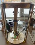 Fig 2: MOST Delta side view
 -
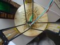 Fig 3: MOST Delta top view


Resolution
[edit | edit source]Smaller nozzles make for tighter corners and smaller line widths. If your print has orifices closely spaced with precise shapes, a smaller nozzle can help deliver a better outcome. However, smaller nozzles plug more easily and they greatly increase print time. Getting a smaller drive gear or using a geared drive (both require redesigning the extruder drive body or using a different one) will help improve resolution further.
Print resolution in the x-y plane changes with distance from the center of the build platform. It's not uniform as it's a function of distance from apexes. If you apply Pythagorean's theorem to a point on the build platform, changing the vertical leg length and watching what happens to the horizontal leg length, you will see it. The resolution gets better if you are closer to an apex. The only problem is, when you are closer to one of them, you are further from the others. So for example when moving towards the W apex (positive Y direction), the resolution in X (controlled by U and V) gets worse, but resolution in Y (mostly controlled by W) gets better. If you care about resolution in both dimensions, the center of the bed is the best place to print. If you care about it in one dimension only, you need to orient your part so that dimension is on a line from the center to an apex, and print it near that apex.
If you have features on the bottom-most layer (the one in contact with the build platform), printing on a raft can help preserve the dimensionality of those features as the bead does not get squished into the glass.
Z is completely different; its resolution is always equal to that of the carriages: 100 steps/mm, so 10μm is the smallest step you can do. This does not depend on the location. Because of the geometry, the error in Z is at most 5μm; i.e. there are no planes spaced 10μm apart with unreachable space in between, but instead the nozzle can go only to a specific point in that 10μm range, depending on the location in X and Y.
Z-axis precision:
MOST Delta (12 tooth T5 belt) operates at 53.33 steps/mm for a z-precision of about 19 microns.
Athena (16 tooth GT2 belt) operates at 100 steps/mm for a z-precision of 10 microns.
Printer capabilities/statistics
[edit | edit source]- Print media: PLA only (heated bed can be added, expanding media options)
- Filament diameter: 1.75mm using a modified Airtripper's Bowden Extruder or a modified Wade's Reloaded Extruder from AndyCart's Cherry Pi III
- Nozzle diameter: 0.5mm (can be changed)
- Print volume: 250mm diameter, 240mm high cylinder
- Melzi print controller w/ integrated SD card reader
Files and Bill of Materials
[edit | edit source]Most of the files required for this design are located here: https://github.com/mtu-most/most-delta
Tools
[edit | edit source]- 5.5mm nut driver and 5.5mm wrench or a pair of 5.5mm wrenches
- 7mm wrench
- 13mm wrench
- Sharp x-acto-like knife
- Small, flat bladed screwdriver
- No.2 Phillips screwdriver (a power driver is best)
- 1.5mm allen wrench
- 2mm allen wrench
- 2.5mm allen wrench
- 3mm (1/8") drill bit
- 8mm (5/16") drill bit
- Sharp pencil
- Sharp point marker
- Tape measure (large calipers >300mm are better), preferably metric
- Soldering iron
- Wire strippers and cutters
- Needle nose or other pliers
Consumables
[edit | edit source]- Two-part epoxy (JB Weld plasticweld recommended)
- JB Kwikweld
- Thread locking compound (Loctite Blue)
- Masking tape
- Muffler cement
- 1/4" kapton tape (recommended)
- White lithium grease (spray or paste)
- Solder
- Flux
- 3/32" diameter heat shrink tubing
Before You Begin
[edit | edit source]Review the process below and collect all of the tools and consumables you need to begin the build. The list of tools above is not necessarily exhaustive.
Software to download and install
[edit | edit source]Software from github.com should be downloaded as a zip file. The link to download the zip file is located in the lower, right corner of the screen when it first opens. It is a button with a cloud icon and the text 'Download ZIP' on it.
All zip files must be extracted prior to attempting to install the software. If unsure how to unzip files, do a web search that includes the name of the operating system you use. There is almost never a need to install additional software to unzip files since all modern operating systems natively include the ability.
- Arduino IDE. Installation packages for popular operating systems are listed on the download page. DO NOT INSTALL the nightly build - instead install the release version (currently 1.0.6). If you use 1.6.0 you may have problems compiling the firmware for the melzi electonics).
- After installing the Arduino software, start the Arduino IDE. This will create your personal sketchbook directory in your user's personal documents home, named Arduino. Some versions ask you for its location when it first starts; specify this place (which doesn't have to exist yet).
- Close the Arduino IDE. Create a new directory named hardware in the newly created sketchbook directory in your personal documents folder.
- Download Arduino for the 1284p zip file and unzip it. Upon unzipping the mighty1284p folder, a folder-in-a-folder is created - copy the folder containing the README.md file (there are other things in the folder, besides just README.md) to the new hardware folder you created in the previous step. Finally, rename the folder in \hardware\ to melzi. After this is complete, copy the file "boards.txt" from \hardware\melzi\ to \hardware\melzi\bootloaders. If everything is correct, the following file exists:
- Windows: My Documents\Arduino\hardware\melzi\README.md
- Anything else: ~/Arduino/hardware/melzi/README.md
- =NOTE= 'There is an Melzi alternative hardware library called Sanguino that can work instead of the above "mighty" library. Place the sanguino folder in the Arduino>hardware directory if you have encounter problems compiling the firmware. If you are still unable to compile be sure you are using the correct version of Arduino IDE (1.0.6)
- Download MOST Delta printer files with Repetier firmware zip file and unzip it. Download the entire library and extract it to a convenient location. The firmware is located in the Repetier directory inside the unzipped folder.
- Download and install Cura slicer. The majority of MOST team members use Cura to slice models for printing. slic3r is an alternative.
- Download and install Repetier Host printer host software.
- Pronterface is a substitute for Repetier-Host. It has GUI programmable features that allow for swift calibration of the delta. It can be used to supplement or replace Repetier-Host. Operating system-specific installations are available:
Building
[edit | edit source]The build process is organized by functional group. The following guide is prepared for a tandem build. Solo builders complete the build traversing the table by row (i.e. complete all tasks in each row of the build process).
For those participating in workshops, some of the assembly is completed before the workshop. Only those parts of the process highlighted green are required. It's important to get the steps requiring epoxying of parts completed early as the epoxy should be well cured by the time final assembly takes place.
Note that all of the pictures in the process can be enlarged by clicking on them.
| Authors | |
|---|---|
| License | CC-BY-SA-3.0 |
| Cite as | Gcanzalo, Hedron (2013–2026). "Delta Build Overview:MOST". Appropedia. Retrieved June 20, 2026. |