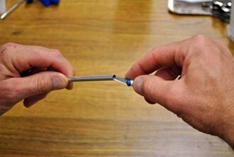
There are six tie rods connecting the end effector to the printer via magnetic ball joints. Each tie rod consists of an aluminum rod with steel ball bearings epoxied to each end:
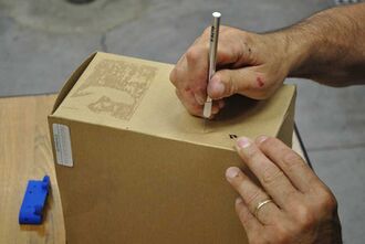
Poking holes in box for standing tie rods in.Prepare a stand for the tie rods by cutting six holes(one for each rod) in a cardboard box or another expendable, flexible but sturdy item that can be used to hold the tie rods in an upright fashion while the epoxy cures.
Reaming tie rod ID.If burrs exist in the inner diameter of the tie rods, ream them with the precision knife so that the ball bearings fully seat in the ID of the tube.
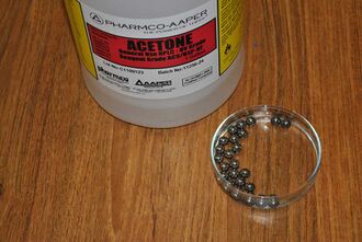
Cleaning ball bearings in solvent.Thoroughly clean the ball bearings with a solvent as they come coated with a corrosion inhibitor that may impede wetting with epoxy. Acetone is a good solvent, isopropyl alcohol will also work.
The ball bearings will be epoxied to one end of the tie rods at a time so start this assembly relatively early in the build to allow time for the epoxy to cure.
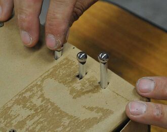
Perform a practice run prior to mixing the epoxy: Push the rods into the holder of choice so that the rod axis is vertical. Place a ball bearing on top of each rod and ensure that the rod and ball bearing remain relatively stationary (don't want the ball bearing to fall off the rod.)
Remove all the tie rods from the stand.
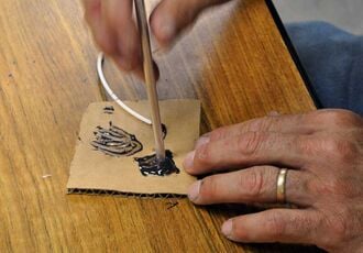
Applying epoxy to a tie rod.Once comfortable that the tie rods with ball bearings on top are secure in the holder and confident in your technique, mix a small amount of epoxy and dip one end of the tie rod in it and then push the dry end of the rod into one of the holes in the holder. Repeat with the remaining five rods.
Epoxying the ball bearings to the tie rods.Carefully dip one part of a ball bearing in the epoxy and place the wetted portion on one of the wetted aluminum tubes. Repeat with five more bearings. Unless there's a terrible mess, don't try to clean up excess epoxy - it can be removed with a sharp knife after it cures.
Keep the excess mixed epoxy at-hand to test set, usually about 15 minutes for quick-set epoxies. Wait until the epoxy has thoroughly set or fully cured before touching the rods or turning over the rods to repeat the process with the remainder of the ball bearings on the opposite ends of the tie rods.
A completed pulley consists of a printed pulley with two M3 nuts and two M3 x 8mm set screws. Pulleys must be secured to the motors before attaching the motors to the motor end assembly:
Pulleys should have a "D" profile shaft opening. DO NOT ream the "D" shaft opening with a drill bit - it is designed to be a snug fit and may require some force to push onto the motor shaft.
Use a 3mm drill to ream the set screw holes. If necessary, use a sharp knife to remove flashing from the nut traps for the set screw. Clean off any protrusions from the cogged portion of the pulleys.
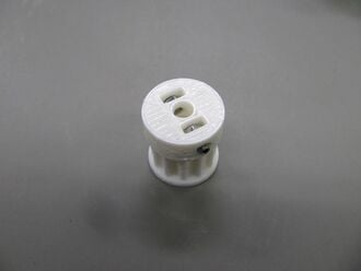
Assembled pulley.Insert M3 nuts into the nut traps in the pulleys, push them all the way to the bottom of the trap using a small screw driver if necessary.
Start the M3 x 8mm set screws into the nuts in the pulleys. Screw them in so they extend into the 5mm hole for the motor shaft, then back them up so the shaft is clear.
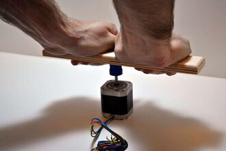
Push pulley on with a helper, like one of the linking boards.Place the motors on the table such that their shafts face upward. Using the back of one of the linking boards, push pulleys, set screws down, onto the motor shafts making sure to align one of the set screws with the flat on the motor's shaft. Push the pulley all the way on the shaft until the gap between the pulley and motor housing is a millimeter or less.
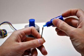
Applying thread locking compound to set screws.Remove the set screws and apply a small amount of thread locking compound to the screws and return them to the pulley. Thoroughly tighten the set screws.