All of the changes to firmware discussed in this portion of the assembly instructions occur in the Configuration.h file. Open the Arduino IDE and select the Configuration.h tab to locate the various definitions referenced below.
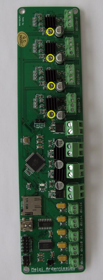
Melzi controller board with locations of fixed resistors highlighted.
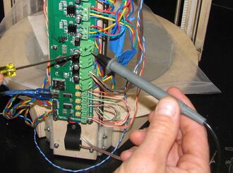
In order to configure firmware so that it controls hot end temperature, both the resistance of the thermistor and the resistance of the fixed resistor on the Melzi board must be known. Note the numbers on the resistors highlighted in the image at right and compare to the magnified images of the resistors:
4.7k-ohm resistor.
If the number is 4700 (4.7 k-ohm), set EXT0_TEMPSENSOR_TYPE to 1.
10k-ohm resistor.
If the number is 1002 (10 k-ohm), set EXT0_TEMPSENSOR_TYPE to 97, uncomment USE_GENERIC_THERMISTORTABLE_1 and ensure that GENERIC_THERM1_R0 is 100000 and GENERIC_THERM1_R2 is 10000.
The stepper motors will not operate correctly if the reference current is set properly on the Melzi controller board. Reference voltage is adjusted by turning the small trim potentiometers (pots) located next to the motor controllers and are highlighted in the picture at right. Most motors will work correctly with a reference voltage of about 0.42V (420 mV). Do not perform the following with 12V power applied to the Melzi board. Only USB power is required.
Disconnect the power supply if connected.
Clamp the negative probe of a DVM into the incoming power ground terminal.Tighten the negative (black) probe of a volt meter into the ground (gnd) screw terminal on the Melzi main power terminal so that both hands are free to manipulate the pot and hold the positive probe. Set the voltmeter to DC volts or DC millivolts.
Insert the mini-B USB cable into the USB socket on the Melzi board and plug it into a computer that is turned on.
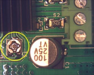
Melzi controller board with reference voltage trim pots highlighted.Close up of reference voltage pot.Locate the motor current adjusting trim pots on the controller board as shown in the pictures.
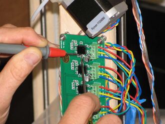
Adjusting the trim pot while measuring voltage.Touch the positive (red) probe of the volt meter to the face of the trim pot and note the voltage. If different than 0.42V (420 mV), turn the pot until approximately 0.42V is measured. The pots are adjusted with a small Philips-head screwdriver or using the corner of a very small bladed screwdriver.
Repeat with the remaining trim pots.
Remove the negative probe from the ground terminal of the power supply and clamp the power supply ground wire and fan ground wire into the terminal.
Do not proceed until each of the following steps has been completed:
Remove the tie rods from their magnetic joints in the carriages to prevent damage if something fails to perform as planned. Lay the end effector and tie rods on the glass build platform.
Verify that controller supply power polarity is correct!
Plug in the power supply to mains (wall socket).
While watching the fan on the end effector, plug the barrel connector into the printer. If the fan does not start turning, unplug the barrel connector. Check wiring ensuring that polarity is correct to the controller and to the fan. If polarity is correct, gently pull on the fan wires in the power terminals on the controller board and reattach them if they're loose. If the fan still doesn't turn, check the fan power wires for continuity. Make adjustments and repeat until the fan turns properly upon application of power.
Start Repetier-Host on the host PC. Make sure that Easy Mode is NOT active.
Click the Connect Button. Select the Manual tab and note the controls will activate if the connection to the printer is successful.
Click the Home button (not X, Y or Z home). Carriages should all move towards the top of the printer. If carriages move towards the bottom, emergency stop the printer. Carriages moving towards the bottom on homing indicates incorrect motor wiring. ALWAYS UNPLUG THE POWER SUPPLY BEFORE DISCONNECTING MOTOR WIRES. Motor drivers on the controller WILL fail if motors are disconnected while 12V power is applied to the controller. Power over the USB is not a problem - the controller can remain plugged into the host computer while rewiring motors. Once motor wiring is correct, recheck homing.
Check that the displayed hot end temperature is logical - it should be around 20 degrees C, room temperature. If it is not, check that the hot end thermistor is wired correctly and that when disconnected from the board, resistance is around 100k ohms. Once satisfied wiring is correct, recheck displayed hot end temperature.
Set the temperature of the hot end to 200 degrees C and watch the temperature of the hot end. If it does not start to climb soon after setting temperature, unplug the power supply from the printer and check that the hot end heating resistor is properly wires. When disconnected from the controller, resistance across the heating resistor should be around 5 ohms. Once satisfied that wiring is correct, recheck that the hot end heats.
With the hot end at 200 degrees C, check the rotation of the extruder drive by clicking on the extrude button in Repetier-Host. The drive gear should rotate towards the Bowden sheath on the idler side of the extruder drive. If the gear is not rotating the correct direction, disconnect power from the printer and check the extruder drive motor wiring. Once satisfied wiring is correct, recheck extruder drive rotation.
Turn off hot end heating.
Reattach the tie rods to the carriages and check that end effector is properly positioned on the tie rods.
Since you are making the printer yourself, it will have slightly different dimensions than any other MOST Delta, and those differences must be accounted for in firmware to ensure the printer works properly. Calibration of the delta printer is exceptionally important. Dimensions entered in the firmware that aren't physically accurate can result in the nozzle crashing into the build platform, cause the printer to produce out-of-scale prints or cause the end effector to not move parallel with the x-y plane.
There is presently no means for performing calibration automatically and an iterative approach is used to provide guidance as to what changes to make in firmware.
"Calibration" is having the correct values in firmware for printable height (Z_MAX_LENGTH), printable radius (printable radius = PRINTER_RADIUS - END_EFFECTOR_HORIZONTAL_OFFSET - CARRIAGE_HORIZONTAL_OFFSET) and tie rod length (DELTA_DIAGONAL_ROD) and the number of steps required to drive one mm of filament (EXT0_STEPS_PER_MM). For simplicity, END_EFFECTOR_HORIZONTAL_OFFSET and CARRIAGE_HORIZONTAL_OFFSET have both been set to zero and only PRINTER_RADIUS is changed when necessary.
All of these values should be reasonably close if the firmware was downloaded from MTU-MOST's github delta repository.
The dimension known with the least precision and accuracy is the printer radius since it is a function of how the printer was assembled. It is also the dimension most difficult to measure. If the linking board lengths are slightly off or they do not butt fully against the stops in the motor and idler ends, the radius in firmware will not be the same as the physical radius of the printer. This difference manifests itself as the effector not moving consistently in the x-y plane and prints that are not dimensionally accurate (out of scale).
Starting with the as-supplied MTU-MOST delta firmware [1]:
From Repetier-Host, open Printer Settings, Printer Shape tab, and set the Printable Height to 300mm. Note that this is approximately 25mm more than it really is, so be careful not to move to values which are too close to 0, as it will make the nozzle crash into the build platform.
Connect to the printer. Note: BAUDRATE 115200
Home the printer by clicking the home icon in the manual control tab.
Drive the effector to 30mm above the firmware's idea of the build platform height (Click the "Easy Mode" button in the upper right hand corner, enter G1 Z30 in the text box above the motion controls on the Manual tab and click Send). This should position the nozzle approximately 5mm above the actual build platform.
Use the 1mm and 0.1mm z-direction controls to carefully move the nozzle closer to the bed until the nozzle contacts the build platform.
If the nozzle cannot reach the build platform, increase Z_MAX_LENGTH in firmware, adding what you think is required to cause the hot end nozzle to come into contact with the build platform, flash the firmware and repeat.
Once the nozzle has come into contact with the bed, use the 0.1mm z-direction controls to move it up until it just clears the build platform. Carefully listening to the printer at this step can help as either a tick and/or hum can be heard when the nozzle contacts the platform.
Move the effector up and down a few times listening for the nozzle to contact the bed until you're confident you've located the contact point. Note the value of z reported by Repetier-Host.
Subtract the z-value reported by Repetier-Host from the current setting of Z_MAX_LENGTH in firmware, flash the updated firmware to the controller and repeat these steps until confident that the printable height is correct.
When Z_MAX_LENGTH is properly set, with z = 0 in Repetier-Host, a piece of paper will just slide under the nozzle with some resistance.
The version of Repetier firmware from MOST Delta printer github repo will have good starting values for printer radius and tie rod length. Once the max Z setting is established, do the following:
Apply a layer of glue stick to the glass build platform.
Slice with settings listed above and save the g-code to a logical, easily remembered location.
In Repetier-Host, load the g-code produced in the previous step and print the model.
To Print for the first time pre-heat your extruder -- disengage your rubber component on your filament driver and by hand load filament through the Bowden tube all the way through your print head. When a few mm oozes out, Re-engage the rubber to push the filament against the drive wheel -- and click print.
Before removing the dogtoy from the build platform, place tape labels marking the x, y and z vertexes of the printer aligned with the marks on the dogtoy.
Remove the dogtoy from the build platform.
Note whether the 'y' and 'z' printed on the dogtoy are mirrored. If they are:
Disconnect power from the printer.
On the controller, switch the wires for the X and Y motors keeping the colors in the same order.
On the controller, switch the wires for the X and Y limit switches.
Reprint the dogtoy and confirm that 'y' and 'z' are correctly printed.
Measure the length of a rectangle on the end of one of the legs with calipers. Note this dimension.
Measure the side of the square on top of the rectangle with calipers and note the dimension.
The difference between these two dimensions should be 15mm +/- 0.2mm. If the difference is greater than 15mm +/- 0.2mm, then follow the steps listed under Modifying Radius and Tie Rod Length, below.
Observe the bottom of the dogtoy (the side in contact with the glass build platform) noting the width of the plastic lines that were squished onto the build platform:
If the width of the lines on just one of the rectangles is noticeably different than the other two, then the end stop screw in the carriage on the vertex aligned with that leg of the dogtoy requires adjustment. If the lines of plastic are very thin, the screw must be backed out of the carriage a bit. If the lines are very thick, the screw must be tightened into the carriage. If the screw is all the way in the carriage and needs to be screwed further in, then first decrease Z_MAX_LENGTH in firmware, readjust all of the carriage end stop screws and reprint the dogtoy.
If the lines in the center of the dogtoy are wider or narrower than the lines at the ends of the legs where the rectangles are, either printer radius or tie rod length needs to be adjusted in firmware. Follow the steps in Modifying Printer Radius and Tie Rod Length in Firmware, below, to correct.
Observe the lines in the top of the dogtoy, again noting their widths. If the width is small and there are gaps between adjacent lines, the extrusion rate is too low and EXT0_STEPS_PER_MM in firmware should be increased. If, on the other hand, the lines are too wide, giving the surface the texture of sharkskin (when rubbed perpendicular to the lines, the surface is rougher in one direction than the other), the extrusion rate is too high and EXT0_STEPS_PER_MM in firmware must be decreased.
Modifying Printer Radius and Tie Rod Length in Firmware
The printer radius and tie rod length in concert affect the scale of the print produced and whether the end effector moves horizontally in the x-y plane. The two values that are set in firmware are DELTA_DIAGONAL_ROD and PRINTER_RADIUS in the Configuration.h file of Repetier firmware.
/* =========== Parameter essential for delta calibration ===================
C, Y-Axis
| |___| CARRIAGE_HORIZONTAL_OFFSET
| | \
|_________ X-axis | \
/ \ | \ DELTA_DIAGONAL_ROD
/ \ \
/ \ \ Carriage is at printer center!
A B \_____/
|--| END_EFFECTOR_HORIZONTAL_OFFSET
|----| DELTA_RADIUS
|-----------| PRINTER_RADIUS
Column angles are measured from X-axis counterclockwise
"Standard" positions: alpha_A = 210, alpha_B = 330, alpha_C = 90
/
The basic relationships are:
Increasing DELTA_DIAGONAL_ROD with constant PRINTER_RADIUS will decrease the scale of the print produced.
Increasing PRINTER_RADIUS with constant DELTA_DIAGONAL_ROD will increase the scale of the print produced.
Start the Arduino IDE.
Open the Repetier.ino file.
Activate the Configuration.h tab.
Search for PRINTER_RADIUS (ctrl-f to open the find dialog).
DELTA_DIAGONAL_ROD is just a few lines above PRINTER_RADIUS.
Description: After plugging in the barrel connector into the printer, the fan does not start turning.
Solution 1: Ensure that the fan power cable is properly (polarity matters) wired into the same connector as is the main power cable. It should not be in the separate FAN connector.
Solution 2: Ensure that the power cable is properly secured in the connector. Pull on it slightly to ensure it is firmly secured.
Solution 3: Make sure the power supply is working - a green light should be visible on the power supply adapter.
Issue: One or multiple motors are not moving when i hit the HOME button in Repetier.
Description: One or multiple motors are not moving when I hit the HOME button in Reperier. The motor does grip (i.e. I cannot move it manually while connected to Repetier), but it does not move in any direction.
Solution 1: ensure that you have properly configured "Configuration.h" with all steps in the Wiki Section Firmware.
Description: nozzle is too close or two far from the bed when printing the first layer.
Solution 1: If the nozzle is lifting just a little bit off the glass (or is traveling too close to the glass such that the PLA isn't extruding from the nozzle) This is most likely fixed by adjusting the stop-screws on the top of each carriage. These are the screws that come into contact with the limit switches at the top of each of the three vertical sections on your printer. If the nozzle needs to me moved up, the stop-screw needs to be adjusted downward. Likewise if the nozzle needs to be moved down, adjust the stop-screw upward.
Solution 2: If the nozzle is moving away from the glass by several mm or even more, then there is probably not enough current getting to the stepper motor at that vertical. Go back to the section on adjusting the trim potentiometers (trim pots) at the top of this page and make sure the voltage is 420mV. If lower than this, adjust the trim-pot for a reading of 420mV or more (like 425mV).
Solution 3: PRINTER_RADIUS parameter could be too large, try decreasing the value (by increments of 1.0 or less). Be careful because delta_radius effects all sides.
Solution n: [nth possible solution.]
Issue: Nozzle not the right distance from Print Bed
My nozzle is too close to the bed on one side and too far away on the other side of the print area
Wiki Section: Finishing
Step: Calibration
Description: The nozzle does not stay the same distance away from the bed as it travels around the print area. This causes problems with printing. If you have tried to adjust the stop screws as described above and you are still seeing problems, then you should level your bed.
Solution 1: If your nozzle is 5mm or more away from any part of the bed, you will need to add wedges to level the bed. If you are able to print, then print out wedges to shim the bed. The best wedges can be found at Thingiverse. http://www.thingiverse.com/thing:28034. These are very small and will print okay as long as they are centered on the print bed. This prints 4 shims, you may want to print more.
Solution 2: If these small shims did not level your bed, then use Cura to increase the size to between 1.25 - 2 times.
Now you should be able to level the bed so that the nozzle is the same distance from the bed at all points in the print area. You may not be able to use the screws and angled brackets would be one suggestion on how to secure the bed to the motor end. It is also possible to use a glue or sealing caulk to attach the bed to the motor end. You want to make sure the shims are glued in place.
Issue: Effector does not move flat across the bed surface