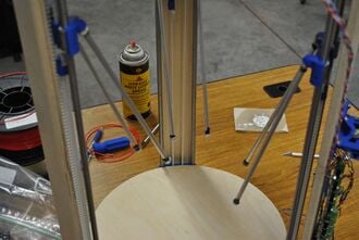
The vertical boards provide additional structural stability to the frame, ensuring printer geometry does not change with time. For best results, the wooden boards should be sealed so as to minimize shrinking and swelling with changes in humidity.
If your vertical boards have mounting holes pre-drilled:
The vertical board with a greater number of holes in it should be mounted on the Y vertex, nearest where wires exit from the motor and idler end assemblies. It should be mounted such that the additional holes are near the motor end assembly.
File:MOST Delta mark vertical boards.JPGMarking location of mounting holes in vertical boards.If the vertical boards have no mounting holes drilled in them, first mark the location of the holes by standing a vertical board against an apex centered over the exposed idler end. Push a 3mm drill bit into the vertical board mounting holes in the idler end from the interior of the printer, forming an indentation in the vertical board.
Remove the vertical board and drill 3mm holes through it at the indentations formed in the previous step.
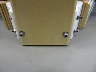
Push M3 x 50mm screws with washers through the holes in the vertical board and then into the idler end.
File:MOST Delta mark motor end vertical board.JPGMarking location of holes in vertical boards, motor end.Invert the printer and with the vertical board loosely secured with screws on the idler end, press indentations into the vertical board this time on the motor end.
Remove the vertical board from the printer and drill 3mm holes at the indentations made in the previous step.
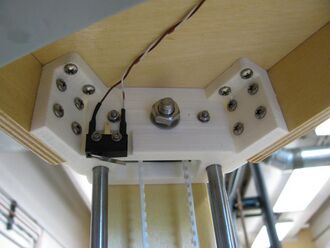
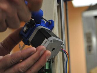
Place M3 x 50mm screws with washers in all four holes in the vertical board and then push the screws into the idler and motor end mount points.
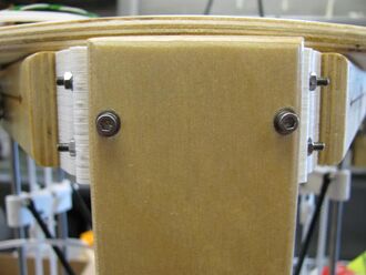
Vertical board mount points, motor end. Secured with nut only.There is just enough room between the motors and screws for a nut, but not a washer. Start nuts on the M3 x 50mm screws and tighten.
Mounting vertical boards.Vertical board secured with washers and nuts on idler end, nuts only motor end.Flip the printer back over and put M3 nuts and washers on the vertical board mounting screws in the idler end. Tighten the screws and nuts.
Repeat with remaining vertical boards.
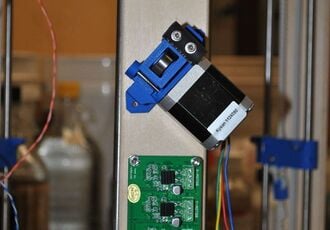
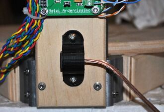
The vertical board nearest where wires exit the motor and idler assemblies will be home to the controller board and extruder drive. Rotate the printer so that board is facing you.
File:MOST Delta mark controller mounts.JPGMarking the location of the controller board mounts.If the vertical board has pre-drilled holes, skip this step. Center the controller against the vertical board about 7cm (2.5 inches) from the bottom of the printer and mark the locations of the mounting holes with a sharp pencil.
Carefully drill 3mm holes through the vertical board at the marks.
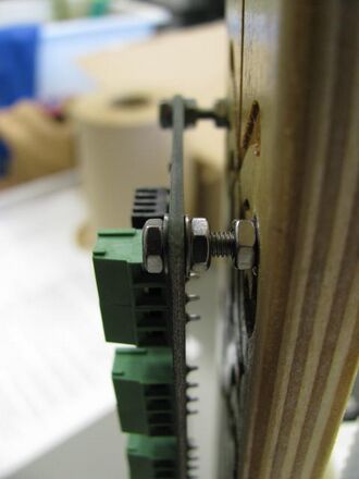
The controller is mounted so that it stands off the vertical board with a series of nuts and washers on M3 x 25mm screws serving as anchors and standoffs. The order of items on the screws, starting from the interior of the printer, is washer-vertical board-washer-nut-nut-washer-controller-washer-nut. When complete, the controller should stand off the vertical board about 1cm and the last nut should be flush with the end of the screw.
Mounting controller to vertical board.Prepare 4 M3 x 25mm screws with washers. Pass the screws through the controller mounting holes in the vertical board so that the screw head is on the interior of the printer. Put washers on the exposed ends of the screws on the exterior of the printer and then start nuts on each screw, but don't tighten them. Put the controller on the screws to ensure that they are properly aligned and tighten the nuts so the screws are firmly affixed to the vertical board.
Remove the controller and start nuts on each screw, then washers. Replace the controller board. Put washers and nuts on each screw and tighten them, securing the board to the printer. The exterior face of the last nut should be flush with the end of the screw.
Placing the extruder drive.About 2cm (1 inch) above the controller, place the extruder drive at about a 45 degree angle, Bowden sheath exiting up and towards your right. With a #6 x 1/2" sheet metal screw, attach one side of the extruder drive to the vertical board.
Extruder drive attached to vertical board.Check the angle of the drive (opposite angled portions of the mount should be parallel with the board) and tighten another #6 x 1/2" sheet metal screw in the unoccupied mounting hole.
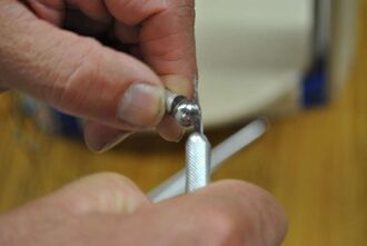
Removing excess epoxy from ball bearings.Clean off epoxy from tie rod ball bearing surfaces that may come into contact with a magnet with your fingernail or the back of the precision knife. Don't remove epoxy from the interface between the ball bearing and the aluminum tube.
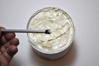
Dipping bearings in grease.Dip each ball bearing in white lithium grease, leaving just a small amount on the ball bearings.
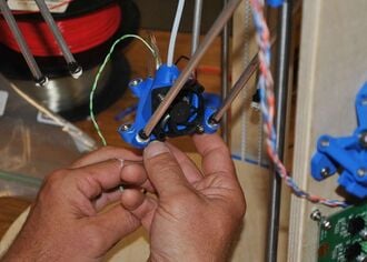
Tie rods engaging magnets in carriages.Place a tie rod onto each magnet in the carriages.
Attaching end effector with fan towards controller.Engage the magnets in the end effector with the opposite end of the tie rods. Have the fan facing the controller board.
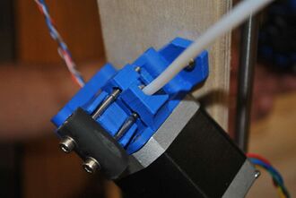
Insert Bowden sheath.Attach the Bowden sheath to the extruder drive.
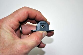
Insert barrel connector into its housing.Slide the barrel connector into its housing with the connector closest to the top of the housing as shown in the picture.
Attach barrel connector just below controller.With a pair of #6 x 1/2" sheet metal screws, attach the barrel connector housing just below the controller.
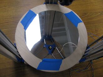
Glass build platform in place.Secure the glass build platform to the bottom wooden round with pieces of tape.


