DO NOT REAM the small holes in the rectangular pockets where the limit switches are mounted (see last steps in this page for clarification). The screws will themselves form threads in the plastic (plastiform threads) when you attach the switches to the idler ends.
The limit switches are held in place with both screws and epoxy. It's imperative that the limit switches do not move once attached to the idler ends. The printer will not home to the same position if switches are loose, causing endless problems with printer calibration.
Clean the idler ends with a sharp knife, removing any protrusions from the faces in the interior of the idler box. Use an M8 drill bit or an M3 threaded rod to ream all of the holes. Clear all protrusions from the linking board mount tabs.
Start the bolt through an idler end.Put a washer on.Put on the bearings.A washer between the bearing and then a washer and nut to secure.The idler is best assembled in steps, inserting a piece, advancing the bolt and then inserting the next piece. The order of items on the bolt, starting from the hex head will be idler end-washer-608zz-608zz-washer-idler end-washer-nut:
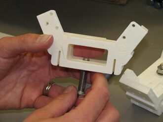
Start the M8 x 40mm bolt through the idler end from the side having the hexagonal relief for the bolt head.
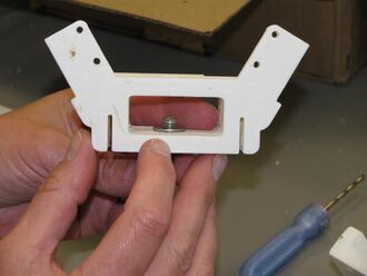
Push the bolt in only until the bolt just extends into the idler box and then place an M8 washer over the end of the bolt.
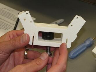
Advance the bolt a bit more and place one of the 608 bearings on it.
Repeat with another 608 bearing.
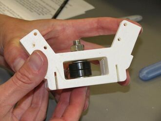
Put an M8 washer on the end of the bolt.
Push the bolt all the way into the hexagonal relief.
Place a washer and finally a nut on the opposite end and tighten.
Repeat with remaining two idler ends.
The following steps are identical to those performed with the motor end assembly; refer to that page for details and pictures.
If linking boards (240mm x 42mm x 12mm) do not have pilot holes drilled in them, follow directions here before proceeding.
With the idler end laying on the table, flanges down, position a linking board so that the pilot holes align with the holes in one of the tabs. The board and idler end must be flat against the table and the board must be firmly against the stop on the idler end. Start four #6 x 3/4" sheet metal screws into the tab and linking board but do not tighten until all of the screws are started and the position of the board is checked – it must be firmly against the stop on the idler mount. Once in position, tighten the screws. (Two screws per tab are probably sufficient, but maximum rigidity and longer maintenance intervals can be assured by using all four screws in each tab.)
Repeat with another linking board on the other side of the idler end.
Continue with remaining linking board and other two idler ends. When complete, the idler ends should form the apexes of an equilateral triangle and the whole assembly should lie flat on the table top, flanges down.
Prepare two M2 x 12mm screws with washers.
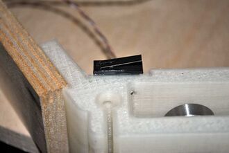
Limit switch epoxied and screwed into pocket.Mix a small amount of the two part plastic epoxy and apply to the switch pockets in the idler ends. Do not apply to the switch as to avoid epoxy getting into moving parts of the switch.
Place one of the assembled limit switches into an epoxied switch pocket with the switch's tab opening towards the idler shaft (see picture). Secure the switch a pair of M2 screws. Repeat with remaining two switches. If the switch's tab opens towards the linking board, the printer will not home correctly.