If your linking boards have any kind of etched design, ensure that the orientation is correct. The flanges for attaching the plywood rounds indicate the top of the printed ends.
Cleaning motor end.Clean the motor end by reaming out the motor mount holes with a 3mm drill and/or an M3 threaded rod. Ream the clamp screw holes with a 3mm drill. Remove any protrusions or flashing from the linking board mount tab with a sharp knife. The knife can be used as a scraper to remove irregularities on the tab face.
If linking boards (240mm × 42mm × 12mm) do not have pilot holes drilled in them, follow directions here before proceeding.
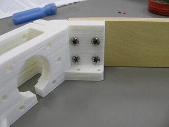
Linking board attached to motor end.With the motor end laying on the table, flanges down, position a linking board so that the pilot holes align with the holes in one of the tabs. The board and motor end must be flat against the table and the board must be firmly against the stop on the motor end. Start three #6 × 3/4" sheet metal screws into the tab but do not start them into the linking board until the position of the board is checked – the board must be firmly against the stop on the motor mount. Once in position, tighten the screws. (Two screws per tab are probably sufficient, but maximum rigidity and longer maintenance intervals can be assured by using all three screws in each tab.)
Repeat with another linking board on the other side of the motor end. A right-angle or stubby screwdriver will be required to engage some of the screws.
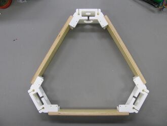
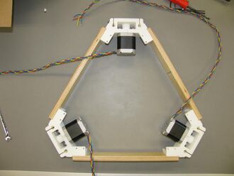
Motor ends and linking boards assembled.Continue with remaining linking board and other two motor ends. When complete, the motor ends should form the apexes of an equilateral triangle and the whole assembly should lie flat on the table top, flanges down.
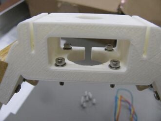
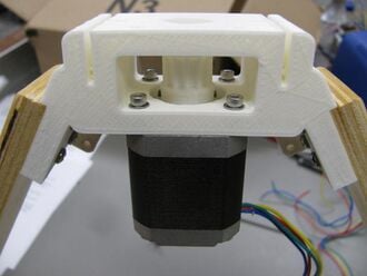
Motor end with screws.Prepare 12 M3×14mm socket head cap screws each with an M3 washer. Stand the motor end assembly up on one linking board such that a motor end is facing upward. Carefully drop a screw with its washer into the motor mount holes.
Motor end with motor.Position the motor with the pulley facing up. The motor's wires should be exiting the motor towards one of the linking boards, not towards the top or bottom of the motor end.
Nearly completed motor end assembly.Braid the motor wires.