DO NOT REAM the holes in the top of the carriages where the limit switch adjustment screws seat!
The belt terminators (assembly steps detailed below) have a narrow passage that the belt passes through twice - that passage needs to be cleaned with the precision knife. (During printing of the terminators, small protrusions form, making it very difficult to slide the belt through the passage.) Additional insurance against loss of belt tension is afforded by the small wire ties on the belt tails.
Wipe down the guide rods with a clean cloth or paper towel to remove any abrasive dust that may damage bearings.
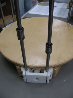
Motor end with guide rods and LM8UU bearings.Place the motor end assembly on the table with the round plywood facing upwards.
Start the 8mm guide rods into the motor end clamps, rotate while pushing into the clamp. The rods should fit tightly in the clamps but not so tightly that beating on them is required to get them to seat; ream the 8mm guide rod holes in each motor end with an 8mm drill bit if necessary. It isn't necessary to push the rods all the way into the clamps yet.
Slide lubricated LM8UU bearings onto the rods – one per rod.
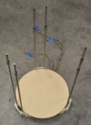
Place the motor end with guide rods on the floor.Lay the motor end with guide rods on the floor. Carefully tap the guide rods all the way into the clamps using a light tool (no hammers!). The sound will change as they hit the bottom of the clamp.
Push on the idler end.Align the guide rods with their clamps in the idler end (plywood round should be up) lining up the limit switch wire exit with the motor wire exit in the motor end assembly. Carefully push the idler end assembly onto the guide rods.
Tap the idler end onto the guide rods.Carefully rap the idler end until all of the guide rods are fully seated in the clamps. As with the motor end, if significant force is required to seat the rods, ream the clamps with an 8mm drill bit rather than risking damage.
Return the printer to the work surface.
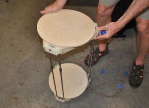
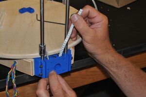
Thread the T5 belt so ends are on the right side.Slide one motor end to the edge of the work surface and push the ends of the belt through the bottom of the motor end so the belt wraps around the pulley. Thread the belt through the left side of the idler box, around the idler and back down towards the motor. The ends of the belt should be on your right side.
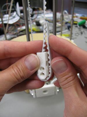
Make sure there's enough belt to pass through the terminator.Completed belt terminator.Push the end of the belt passing over the idler through the slot in the fixed (long) belt terminator, wrap the belt around the rounded portion and then back into the slot. Push the belt into the slot such that it assumes the bend required to go back through the slot and pull the belt terminator tight. You are going to match the long belt terminator to the bearing holder on the rails - so the long terminator needs to be facing down on your right with the larger diameter screw recess facing you.
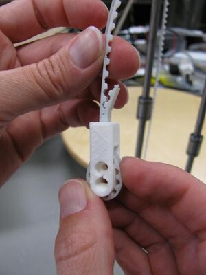
Completed belt terminators. Make sure the larger diameter screw recess is facing out towards you.Repeat the process with the free (short) belt terminator on the opposite end of the belt.
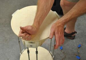
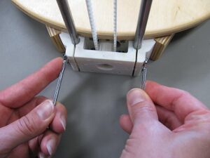
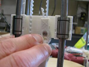
Large wire tie belt tensioner.Start a large wire tie through the free (short) belt terminator starting from the interior of the printer. Ensuring that the belt is not twisted, thread the end of the wire tie through the fixed (long) belt terminator's larger hole and secure the wire tie. Do not pull the wire tie tightly yet.
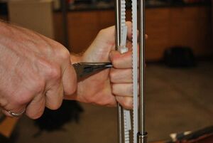
Pull the large wire tie tight to tension the belt.Rotate the printer 180° so that the end of the wire tie is pointing towards you. Grip the fixed (long) belt terminator with your left hand and the end of the wire tie with a pair of pliers. Pull firmly on the end of the wire tie, building tension in the timing belt. Pull reasonably hard but not so hard as to break the wire tie. The belt should be tensioned such that it can be plucked similar to a guitar string.
Using diagonal cutters, cut off the tails of belt that extend out of the terminators so that only about 11-2 cm of tail remain.
Repeat belt installation and tensioning with remaining two apexes.
Tighten guide rod clamps on motor and idler ends.Tighten the M3 nuts on the threaded rods passing through the apex end clamps so that the 8mm guide rods are held firmly by the clamps. Some cracking sounds are normal, but don't tighten to failure.
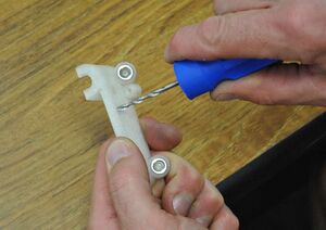
Reaming carriage belt mount hole in web. DO NOT ream the holes in the top of the carriages where the limit adjustment screws seat!Clean a carriage with a sharp knife, removing the floor layer printed in the guide rod passages and removing protrusions from the interior of the LM8UU saddles. Remove flashing from the top of the carriage at the guide rod recesses. Ream the 3mm hole in the web with a 3mm drill bit or M3 threaded rod.
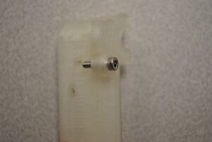
End stop screw plastiformed in carriage.DO NOT ream the screw holes for the limit switch adjustment screws! Plastiform an M3 x 12mm screw into the hole located on one side of the magnet mount. The screws should be tight in the threads, requiring a wrench to turn them. The head of this end stop screw should sit proud of the top of the carriage as shown in the picture.
Test fit the carriages on their guide rods: Put each of the carriages on the rods but not over the LM8UU bearings. Slide the carriages up and down the rods taking note if there is resistance. If there is, remove a small amount of material from the guide rod pockets in the carriages with a sharp precision knife. Repeat the test and adjust the pockets until each of the carriages slides freely on the guide rods.
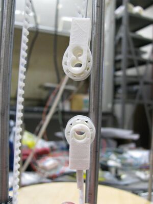
Carriage snapped onto LM8UU bearings.With the end stop screw facing upwards and towards the interior of the printer, snap the carriage onto the LM8UU bearings on the guide rods on one of the apexes. Repeat with remaining carriages.
Run the carriages and bearings up and down the guide rods checking that there is not too much friction. If they are difficult to move, check the clearance between the carriage and guide rod. Snap off carriages that are hard to move and enlarge the guide rod opening with the precision knife.
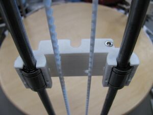
Tighten guide rod clamps on motor and idler ends.Align the carriage with the fixed (long) belt terminator so that the hole in the terminator mounting hole aligns with the hole in the carriage web. Secure the fixed terminator to the carriage with an M3 x 16mm screw and nut; place a washer on the screw on the nut side only. The head of the screw should be fully seated in the recess in the belt terminator.
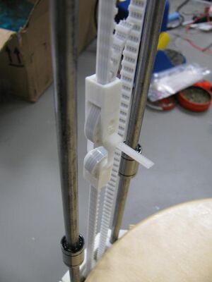
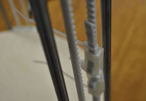
Small wire ties keeping belt secure.Mesh the tail ends of the belt with the belt exiting the belt terminators and secure the tails with a small wire tie as shown in the picture (picture does not show carriage). Cut off the tail of the wire tie flush with the wire tie clamp - no tail should project into the printer's interior.


