Polarity refers to DC power - one of the conductors is positive (+) one is negative (- 'ground' on the controller board). Steps where polarity is a consideration are noted - pay close attention and make sure that the positive and negative conductors are in the correct locations before applying power to the printer!
Organize the wires from the end effector. Wire tie them to the Bowden sheath at regular intervals.
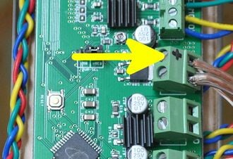
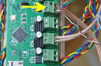
Mark the POSITIVE terminal on the controller.Locate the supply power terminals on the controller taking care to identify the polarity of the terminals. The identity of the terminals may be difficult too read - use a magnifying glass if necessary. Clearly mark the POSITIVE terminal with a permanent marker.
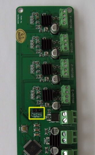
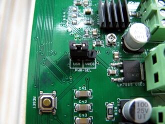
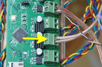
The Melzi power source jumper is in the middle of the board.Closeup Melzi power source jumper. Note that it is in the USB power position.Ensure that the shorting block on the controller power supply selector pins in the middle of the printer controller are set so the left-most pair of pins are shorted (controller powered over USB) as shown in the picture.
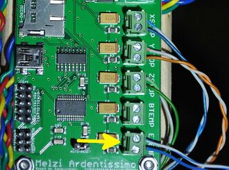
The jumper at the bottom of the board enables autoresetting of the controller, which is required for uploading firmware. Set the jumper over both pins so they are shorted.
Wires can be tucked behind the controller board and secured to the standoffs with wire ties to keep things neat. Secured and well bundled wires are less likely to get entangled.
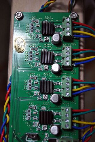
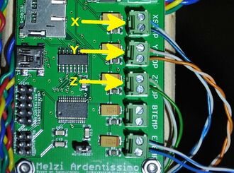
Follow the wiring carefully - click on picture to zoom in.Wire the motors as shown in the image, wiring the drive motors to X, Y and Z as marked (note that reversing X and Y will result in mirrored prints). The extruder motor is likewise connected to the controller. If motor leads are colored differently than those shown, motor wire pairs that are connected to the motor poles can be identified by touching pairs of motor wires together and noting if additional force is required to rotate the motor shaft. Wire pairs that increase resistance to rotation should occupy adjacent terminals (e.g. the pairs shown in the picture are red-green and blue-yellow).
There is no polarity for limit switches and thermistors.Connect the limit switch conductors to their respective axes e.g. the limit switch above the X-motor is attached to the X-axis limit switch, etc. There is no polarity concern.
Wire hot end thermistor.Connect the hot end thermistor to its respective connectors on the controller board. There is no polarity concern.
Wire hot end resistor.Connect the hot end power resistor to its respective connector on the controller board (there is no polarity concern).
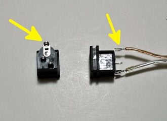
Note the color or marking of the conductor soldered to the positive terminal on the barrel connector (marked).Note markings or conductor colors on the power cable coming from the barrel connector. The POSITIVE conductor is soldered to the largest terminal at the top of the barrel connector (marked in photo).
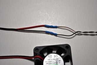
Note the color of the 24ga wire soldered to the fan - brown-white in this picture.Note the color of the 24ga wire soldered to the red (POSITIVE) wire of the end effector cooling fan.
Attach power cable - POLARITY MATTERS!. WARNING: Reversing polarity at this step will likely result in destruction of the controller upon application of power. Locate the POSITIVE supply power terminal on the controller and secure both the POSITIVE conductors from the fan and barrel connector to it. Secure the negative conductors from each in the remaining controller supply power terminal.