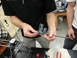
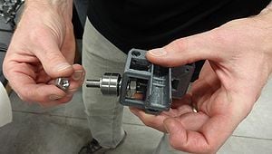
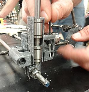
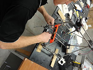
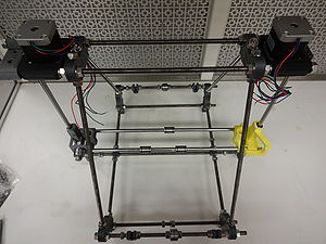
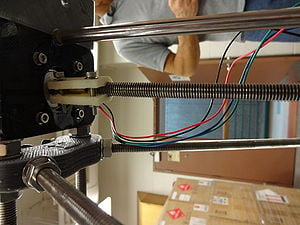
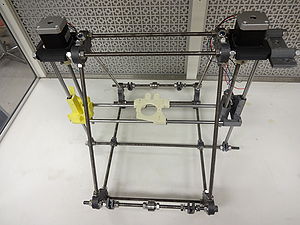
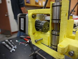
MOST RepRap (Michigan Tech's High School Teacher Seminar RepRap)
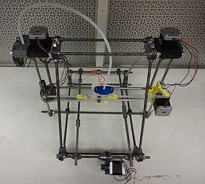
This page describes how to build a MOST RepRap open-source 3-D Printer. It is a variant of the Prusa Mendel [1]. You should be able to build this model for under $600 in under 24 hours working alone from this page.
Before You Begin[edit | edit source]
The pictures in this iteration of the MOST build procedure do not follow part color coding. Future updates will contain pictures of parts following this coding scheme:
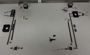
- Silver: Frame (vertexes, two bar clamps, six wire holders, two Melzi board mounts)
- Black: X-axis (motor and idler ends, x-carriage, two belt terminators, one belt clamp, one end stop holder, one 12 tooth T5 pulley)
- White: Y-axis (motor mount, two belt terminators, one end stop holder, four bar clamps, y-carriage corners and bearing saddles, one 12 tooth T5 pulley)
- Yellow: Z-axis (two z-axis motor mounts, one z smooth rod clamp, two z-motor couplings, two bar clamps, one end stop holder)
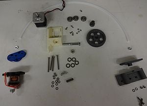
- Red: Extruder (extruder drive body, idler and gears, extruder drive spacer with Bowden nut trap, extruder drive spacer without nut trap, extruder drive mount, Budaschnozzle Bowden mount)
Note that printed parts expected to function adjacent heated components (y-carriage parts, x-carriage, Budaschnozzle Bowden mount, extruder drive spacers) are printed with ABS. PLA tends to soften and lose integrity upon even minor heating and will certainly fail in critical components such as the Budaschnozzle Bowden mount.
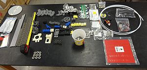
Before assembling make sure you have all the parts necessary in the BOM and the necessary tools.
Main alterations from standard Prusa Mendel RepRap[edit | edit source]
- A lightweight carbon fiber rod y-carriage that has the capacity to increase y-travel to 250mm and increase print speed
- 3mm Bowden extruder and we are using a Lulzbot pre-built extruders Budaschnozzles
- New z-drive coupling
- There are other minor mods like redesigning the end stop holders using non-standard x-axis ends and the handy little belt terminators for providing tension belts while reducing the length of the belts
- Cost was kept down by using the Melzi board, but partially offset by the more expensive pre-fabricated Lulzbot Budaschnozzle for the extruder.
Tools[edit | edit source]
- Wrenches: (2) 13mm, 7mm, 5.5mm
- Hex key (Allen key) set: 5, 4, 3, 2.5, 2, 1.5mm
- Measuring tape
- Needle nose pliers
- Utility knife blades - used as scrapers to clean the sharp edges of printed parts
- Drill bit size 5/16" (8mm), #9 (0.196", or 5mm) 1/8" (3mm) (to clean out holes)
- Wood jigs (290mm, 234mm) pictures below
- Gloves – to prevent cutting fingers on threaded rod and sharp edges of printed parts
- White lithium grease (to lubricate bearings)
- Torpedo or bubble level
- File
- M8 die recommended to clean up cut threaded rods
- zip ties
- small vice-grips to hold drill bits for reaming
- pencil sharpener
- silver epoxy
- wire strippers
BOM[edit | edit source]
- Print all of the following STLs. Printed parts are printed with PLA unless otherwise indicated by (ABS) following the file name.
Printed Parts[edit | edit source]
The following plates are functionally organized and named to indicate the print media to be used to produce a color-coded print. Color coding is intended to facilitate assembly and color coded builds will be used at future build workshops. While printing the parts using color coding is optional, the print material should be as indicated in the file name; ABS is recommended where there is exposure to elevated temperature.
| File | Summary |
|---|---|
| White abs Y.stl | Y-axis ABS parts (white or natural ABS) |
| White pla Y.stl | Y-axis PLA parts (white PLA) |
| Black abs X.stl | X-axis ABS parts (black ABS) |
| black pla X.stl | X-axis PLA parts (black PLA) |
| Red abs ext.stl | Extruder ABS parts (red ABS) |
| Red pla ext.stl | Extruder PLA parts (red PLA) |
| Yellow pla z.stl | Z-axis PLA parts (yellow PLA). Two required but will produce extra end stop holder and rod clamp. |
| Silver pla frame.stl | Frame PLA parts (silver PLA). Two required. |
Frame[edit | edit source]
Printed parts[edit | edit source]
4 frame-vertex-foot.stl
2 frame-vertex.stl
2 bar-clamp.stl
Steel[edit | edit source]
6 370mm M8 threaded rod
4 294mm M8 threaded rod
3 440mm M8 threaded rod
66 M8 nut
70 M8 washer
Z-axis[edit | edit source]
Printed parts[edit | edit source]
2 z-motor-mount.stl
2 parametric-coupling.stl
2 bar-clamp.stl
1 end-stop-holder.stl
1 rod-clamp.stl
Steel[edit | edit source]
4 LM8UU bearing
2 350mm 8mm smooth rod
2 210mm M8 threaded rod
10 M8 nut
16 M8 washer
7 M3x20mm screw
8 M3x10mm screw
15 M3 washers
7 M3 nut
2 M2x14mm screw
2 M2 washer
Electromechanical[edit | edit source]
2 NEMA17 1.8 degree stepper motor
1 Limit switch
X-axis[edit | edit source]
Printed parts[edit | edit source]
1 x_end_plate.stl
1 xcarriage.stl (ABS)
1 belt-clamp.stl
2 belt_terminator.stl
1 end-stop-holder.stl
1 12t_T5_pulley.stl
Steel[edit | edit source]
2 608ZZ bearing
2 385mmx8mm smooth rod
1 50mmx8mm threaded rod
2 M8 nut
2 M8 washer
2 M8 fender washer
3 M3x25mm screw
3 M3x20mm screw
5 M3x10mm screw
9 M3 nut
9 M3 washer
2 M2x14mm screw
2 M2 washer
Electromechanical[edit | edit source]
1 NEMA17 1.8 degree stepper motor
1 Limit switch
Y-axis[edit | edit source]
Printed parts[edit | edit source]
1 Y-Motor_bracket.stl
2 belt_terminator.stl
1 end-stop-holder.stl
1 12t_T5_pulley.stl
1 y_carriage.stl (ABS)
Steel[edit | edit source]
4 608ZZ bearing
4 LM8UU bearing
2 420mm 8mm smooth rod
12 M8 nut
14 M8 washer
13 M3x10mm screw
5 M3x20mm screw
15 M3 nut
32 M3 washer
2 M2x14mm screw
2 M2 washer
Electromechanical[edit | edit source]
1 NEMA17 1.8 degree stepper motor
1 Limit switch
Extruder[edit | edit source]
Printed parts[edit | edit source]
1 wades_plate.stl
1 hearingbone_gears.stl
1 exdrive_spacer_direct.stl (ABS)
1 spacer_w_insert.stl (ABS)
1 prusa_extruder_mount.stl
1 buda_mount.stl (ABS)
Steel[edit | edit source]
1 M8 or 8mm smooth rod, 25mm long for idler
4 M4 x 50 hex cap
10 M4 washers
1 hobbed bolt
4 springs
6 M4 nuts
2 M4 x25mm screws
1 8mm nut and washer
3 608 bearings
4 M3x10mm screws
4 M3 washers
1 M3 x10mm grub screw
1 M3 nut
2 M6 nut
Electromechanical[edit | edit source]
1 NEMA17 1.8 degree stepper motor
Assembly Instructions[edit | edit source]
Frame Triangles[edit | edit source]
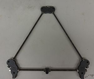
There is an equilateral triangle on each side of the HS RepRap. Initial assembly will be very loose - don't tighten the nuts or be overly concerned about their placement during first assembly steps; everything will be tightened up and properly placed in future steps.
Parts Required (per triangle)[edit | edit source]
- 2 RP footed frame vertices
- 1 RP frame vertex (non-footed)
- 1 RP bar clamp
- 3 370mm M8 threaded rods
- 14 M8 nuts
- 14 M8 washers
- 290mm wood jig
Follow image and build two triangles each with 2 footed frame vertices, 1 unfooted frame vertex, 1 rod clamp on the threaded rod connecting the two footed vertices, 14 M8 nuts, 14 M8 washers and 3 370mm M8 threaded rod.
Using the 290mm long jig, space each vertex from its neighbors and tighten the nuts so that a rigid triangle is formed. The jig should be placed such that it is against the printed vertices near the washers, but not on the washers.
To make sure the holes line up, you can lay the triangles on top of each other and insert six M8 bolts through the each hole in the vertices. The bolts should go through holes in both vertices easily, adjust the frame a little if necessary.
Building the bulk of the frame[edit | edit source]
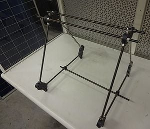
When you build this make sure you do not tighten down any of the bolts - it should be super loose to start.
Parts needed[edit | edit source]
- 3 440mm M8 threaded rods (the long ones),
- 16 M8 washers a
- 16 M8 nuts
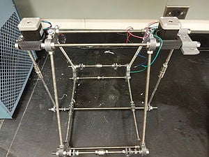
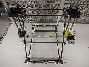
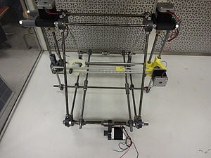
Put the frame together with the long rods as shown in the picture.
The Y-axis (Back & Forth)[edit | edit source]
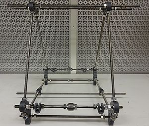
The y-axis consists of two sides each consisting of a pair of threaded rods with only slight differences in what is placed on these rods. The assembly of the top rods is identical whereas the lower rods are assembled slightly differently. Note the distinction between motor end and idler end - the motor end has additional nuts and washers on the lower rod.
Building the y-axis upper rods[edit | edit source]
If difficulty threading, chase the threads with a M8x1.25 die or jam a pair of nuts on one end of the threaded rod and use wrenches to increase the amount of torque applied.
Parts needed for each side[edit | edit source]
You will need two sets of the following
- 10 M8 washers
- 2 608 bearings
- 8 M8 nuts
- 294 mm M8 threaded rod
- 2 rod clamps
From left order of assembly (assembly is symmetric about the 608 bearings): washer, nut, nut, washer, rod clamp, washer, nut, nut, washer, washer, 608 bearing, 608 bearing, washer, washer, nut, nut, washer, rod clamp,washer, nut, nut, washer.
Build two of these. Mount them through the upper holes of the bottom, footed vertices. Add a washer and nut to each end, but leave the assembly loose to accommodate placement of parts during later steps.
Building the Bottom Rods[edit | edit source]
Parts needed for motor end[edit | edit source]
- 2 - 294 mm M8 threaded rod
- 6 M8 washers
- 6 M8 nuts
Parts needed for idler end[edit | edit source]
- 2 - 294 mm M8 threaded rod
- 4 M8 washers
- 4 M8 nuts
Assembly[edit | edit source]
Motor end, bottom rod (motor side): washer, nut, nut, washer, washer, nut, nut, washer
Idler end bottom rod (idler side): washer, nut, nut, washer
Mount rods to the frame with a washer and a nut on each side - it doesn't matter which side at this point of the build. Remember to leave the assembly loose at this point - tightening will take place later.
The Z-Axis (Up & Down)[edit | edit source]
Obtain all the z-axis components
Assemble the z-motor Mounts[edit | edit source]
Face the y motor mount towards yourself and then on the right put on z motor mount with a washer, washer nut. Use the smaller jig to get the distance between the two triangles more or less right. Then put on the second z motor mount on the left with washer washer nut. Mount the motors to the motor mount with M3 screws.
Put a nut, washer, rod clamp, washer, nut on each side of the bottom threaded rod.
Then put the vertical smooth rod through the bottom rod clamp and use the level to adjust the bottom rod clamps to the correct position. Lubricate LMU88 bearings with white lithium grease. Attach the smooth rod from the bottom to top on both sides with 2 LMU bearings on each smooth rods as seen in the picture.
The X-Axis (Left-Right)[edit | edit source]
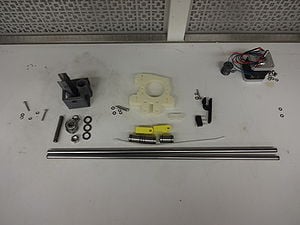
Obtain all the x-axis components.
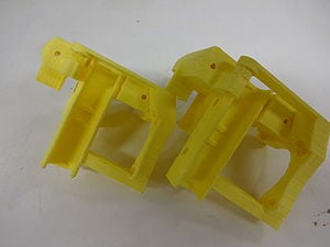
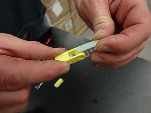
Clean up motor end of the x-axis with a knife or needle-nose pliers as seen in the yellow images (before right and after left ). You also need to use an knife to dig out a hole in the big nut trap.
Load M3 nuts into the x-axis and use a threaded rod to push through to the bottom and then thread the screw for both of the deep nut traps.
Next construct the idler as shown in the image. Nut, washer, plastic, large washer, 2 bearings, large washer, nut.
Next load bearings on the motor and idler sides (two on each of the z axis) and mount on vertical smooth rods.
Slide the two smooth rods through both of the plastic x axis sides. Mount the x-stage with 3 bearings on the two smooth x rods (2 bearings on the motor side and one on the other). Then put M3x20s all the way through the idler side with washers and bolts.
Check the level of the x-axis. You can also use a plumb bob to ensure that the vertical smooth rods are directly vertical. Do on both sides. The stage should slide up and down effortlessly. Tighten it all down.
Attaching X-stage to Z steppers[edit | edit source]
Take the couplings that couple the shaft to the motor and clean them out. These couplings take a pair of M3x20 screws and M3 nut and M3 washers and these fit into the nut traps on the coupler. Mount the coupler and the z axis threaded rod (210mm M8 threaded rod) as seen in the picture. Note couplers printed in ABS for flexibility. The coupling ends may need to be reamed out with a drill bit, however ensure that there is a snug fit after reaming and prior to tightening the screws.
Pull x axis up – use a wire to temporarily tie it to the top frame and put 2 M8 nuts on the z axis threaded rod on both sides. Release the x-axis back onto the nuts. Use 3 small zip ties to tie the x-axis stage to the 3 bearings.
Mount the pulley to the x-axis stepper motor with M3 trap nuts and M3x10 grub screws. Mount the motor with 3 M3 x10 screws.
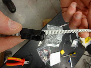
Cut 875mm of belt and attach belt terminator as seen in figure. Pull on the belt carefully and the teeth will mate.
Run the belt through the pulley on the motor side and then the idler and put on the second belt terminator. Use a ziptie to tie both terminators together. The terminators should be on the top as seen in figure. Use a belt clamp and two M3X20 nuts,washers and bolts to attach the belt to the x-axis stage. When attaching make sure that the belt terminators and the stage are on opposite sides of the printer (as seen in picture).
Attaching y stage[edit | edit source]
Slide out the two smooth rods for the bottom y stage and put on 2 LMU bearings on each side. Make sure the smooth rods are on top. Snap on the y-motor mount in between the double sets of washers on the base (see image). Mount the pulley with two M3 nuts and M3 grub screws to the last stepper motor. Mount the motor to the y-motor mount using 3 M3 washers and screws. Note – be careful about the orientation of the pulley on the motor.
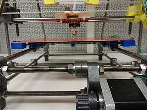
Super-Slim Y-stage[edit | edit source]
BOM[edit | edit source]
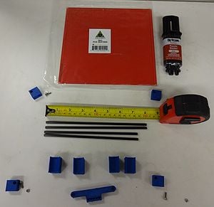
- 2 of each carbon fiber rods 200mm and 185mm (Carbon fiber rods are from goodwinds.com/merch/list.shtml?cat=carbon.pultrudedcarbon item no. 020961.)
- 4 M3x10mm screws
- 4 M3 bolts
- 4 corners, 4 saddles and 1 spacer (or print plate01.stl)
- plastic weld epoxy
- heated bed
- thermistor
M3 nut and screw to
long rods parallel to
Instructions[edit | edit source]
- Print four corners, four saddles and one spacer (or print plate01.stl).
- Measure carbon fiber rods.
- Cut the rods with a utility knife (score the rod to length then roll the rod under the blade while applying pressure) works nicely. You can also finish off with a hacksaw (drag it back slowly – carbon fiber will tear).
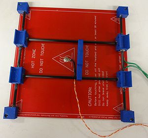
- Put a M3 nut and M3x10mm screw into each corner. Use the heated build platform circuit board to space the corners correctly.
- Push two saddles onto a rod
- Put one of the corners onto a corner of the board with a nut. Put the trace side up. The Deep holes on the corners must be facing up.
- Push one end of the rod with the two saddles on it into the corner on the board.
- Push another corner onto the opposite end and attach it to the board. Repeat on other side.
- Put the entire stage together dry. Make sure everything fits and is in the right direction. Make sure tat the holes for the saddles are facing inwards. If it does, remove one corner piece from the board and carefully apply a little epoxy to the ends of the rod, push the corner pieces back on and reattach the corner piece to the circuit board with a nut. Rotate the rod and move fore-aft to get the epoxy smeared around.
- Repeat the process on the other side. Put the saddles on first!
- After the epoxy has set, move the saddles so that they are relatively equally spaced 1/3 the length of the rod.
- Put the other two rods through the spacer.
- Loosen the nuts on the corner pieces so the parallel rods can be moved some.
- Push the cross rods into the holes on the saddles and tighten the nuts so that the whole assembly is relatively fixed to the board.
- Finalize spacing of the saddles pushing the spacer from one side to the other. When happy with their position, apply a small dab of epoxy to each saddle/parallel rod to affix the saddle to the parallel rods. Let the epoxy set.
- Loosen the nuts, remove the cross rod ends from the saddles and apply epoxy to the ends of the cross rods. Reinsert the cross rods into the saddles and rotate them and push them side to side to smear the epoxy. Tighten the nuts so the assembly is rigid and fixed.
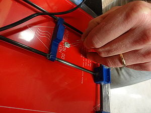
- Use silver epoxy to mount a thermistor to the heating stage as shown in photo.
- Space the y-axis guide rods so that the saddles fit snugly on the bearings, tighten everything up, affix the bearings to the saddles with small zip ties.
- Align the y-axis drive belt with the dog and push the belt into the dog. Move the carriage fore and aft to assure motor and idler are aligned properly and tighten everything up.
Ensure that the y-axis is plumb with the x-axis – can use calipers or measuring tape to ensure equidistant on each side between x an y slide rods.
Optional: If you want you can use 4 M3x20mm screws instead of 4 M3x10mm screws for attaching the bed. This will require 8 more M3 nuts (12 total) but allows for easy bed leveling in the future. To do this just put an M3 nut in the nut trap on the corner pieces and screw the M3x20 until it is tight. Then screw another M3 nut down the M3x20 and put the heated bed on top and secure with another M3 nut. Do this for each corner piece. You may want to do the initial setup to make sure the layup is proper and epoxy is set before changing.
Additional pieces[edit | edit source]
- 125mm y belt
- 2 belt ends
- zip tie
- m3 x20mm and 2 m3 nuts and washers
Mounting y-axis[edit | edit source]
Orient y-motors facing you, push the nuts to the left side of the frame and tighten jam them up.
Excess y-axis guide rods – pull it towards the side with the motor and tighten down.
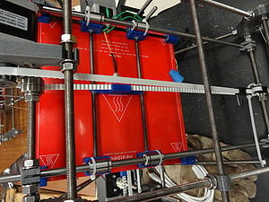
Push 2 wire ties through each saddle (may need pliers to pull them through. Mount the board to your printer with the wires facing the Melzi and line up all your bearings. (If z-axis is getting in the way – move the z-axis nuts up).
Tighten down the wire ties over the bearings.
Slide y-axis back and fourth – while looking to minimize friction and then tighten the m8 nuts in place. The y-axis should slide back and fourth with very little drag – adjust y-rods as needed and slide it back and fourth until in slides smoothly.
- note:alter to have only one wire tie per saddle.
Cut y belt to 125mm long.
Trim ends of belt so that it terminates with a tooth. Put belt terminators at both ends of the belt. Loop around y motor shaft and idler shaft and then tie into place with a zip tie so that it is somewhat loose.
Tilt the printer on the side and push the y-stage all the way to the limit switch and the two belt terminators to the other side. Then slip the teeth of the belt into the dog on the stage.
Move the m8 nuts on the main rods to assure that the the y motor and the idler until the belt does not walk when you move the y-axis back and fourth. When everything is aligned, tighten the bolts down and then pull on the zip tie to make the belt tight enough to 'twang' like a guitar. Put the glass or mirror pre-cut to size on top of your bed and hold in place with 4 small binder clips.
The Extruder[edit | edit source]
BOM[edit | edit source]
Printed parts
- Wade's gear big and small
- 1 extruder body
- 1 spacer
- 1 extruder mount
- 1 hot end mount
- 1 motor spacer (thin)
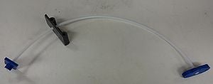
- 1 Bowden sheath 2ft long (8th inch OD,8th by a quarter ID, PTFE tubing)
- 2 M6 nuts
- 3 608 bearings
- 5 m8 washers
- 1 m8 locknut
- 1 Hobbed Bolt
- 1 inch threaded rod idler shaft
- 4 M4X50mm screws
- 1 Budaschnozzle 1.2 0.5 mm(LulzBot)
- 4 springs
- 6 m4 nuts
- 10 m4 washers
- 2 m4 x 20 mm screws
- 1 stepper motor
- 4 m3x10mm screws
- 4 m3 washers
- 1 set screw
- m3 nut for small wade gear
Instructions[edit | edit source]
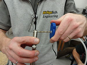
Use a pencil sharpener to trim down Bowden sheath
Follow image to plastiform threads at both end of the sheath
Clean out extruder body holes Mount M6s in the holes of the extruder mount and hot end mount (see image) Screw the long m4s screws on the extruder body and the idler carriage (see image) – put all the way on then take off – that piece you want to be freely moving.
Mount set screw and m3 nut in small gear and mount that on the stepper motor shaft.
Mount the motor to the extruder body loosely with m3 screws.
Mount the extruder body on the extruder mount before attaching it to the frame using 2 m4 screws washers and nuts. This will ensure that before you put on the gears you will be able to mount it on the printer. Warning: If you do not do this step you will need to take the whole extruder apart
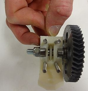
Mount main large hearing bone gear. Take hobbed bolt, gear, 2 to 4 washers, 608 bearing – push through extruder body, 608 bearing, washer and a lock nut. The number of washers will depend on your hobbed bolt. You want your filament to be centered on the hobbed part of the bolt (see image).
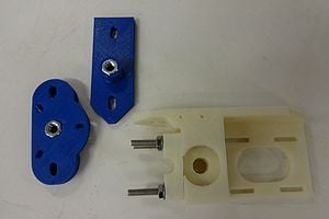
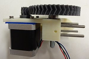
Match up gears. To do this you may need the stepper motor spacer (in blue in image - can adjust open-SCAD for perfect fit). Match the gears up and screw the stepper motor to the extruder body with 2 m3 screws – tighten down. Then push the hob bolt out of large gear – catch the washers as they fall. Then screw the other two m3 screws and washers down and put the hobbed bolt and washers back together.
Mount it all to the frame with the M8 bolts and washers.
Screw the sheath down over the m4 nut in the extruder holder and trim off with knife to be flush with nut. Run an 1/8th drill bit through the hole.
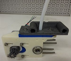
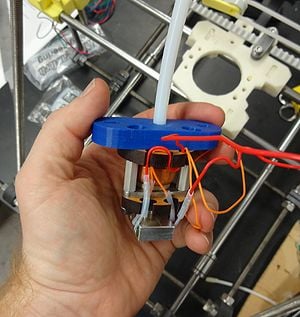
Put the sheath through the extruder drive mount (grey) and then screw the sheath down over the m4 nut in the drive holder (blue). Trim with knife and run the drill bit threw it. Note the blue parts are ABS.
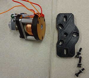
Remove the printed plastic base on the Budaschnozzle (see image is in black). Keep that black piece in case you ever want to direct mount your extruder to the x-axis.
Attach the extruder mount (blue piece) to the Budaschnozzle using the same screws. Tighten the whole Budaschnozzle down.
Attach Budaschnozzle to the x-axis using 2 m4x20 screws, nuts and washers.
Electronics[edit | edit source]
BOM[edit | edit source]
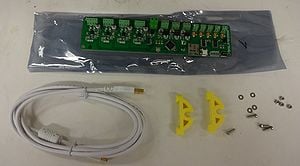
- Melzi boards
- 2 printed Melzi mounts (printed)
- 4 m3x10 screws
- 4 m3 bolts
- 4 m3 washers
- wires
- heat shrink tube
- lighter or heat gun
- zip ties
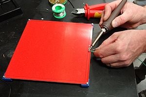
How to Solder Cut the thermistor leads to have one shorter than the other. Get 3 feet of 2 conductor wire. Then cut your conductors to the same length difference. Cut 1 cm of heat shrink tubing to completely cover the first lead and a slightly larger diameter heat shrink tube to go over the first and the other wire. String them both on the wire. Strip about a half cm of wire and overlap the thermistor leads with the wire. Solder the wire to the thermistor lead by tinning the surface first – do a butt joint. Put the first heat shrink tube down and use a lighter to shrink it. Then solder the second wire. Finally put the longer heat shrink tube down over the second wire and first heat shrink tube – and shrink it in place with the lighter.
Other thoughts about wiring When using the Melzi board, pay particular attention to polarity of the incoming power. The board is marked and black goes to ground (gnd)! Fail to do this and risk smoking your board.
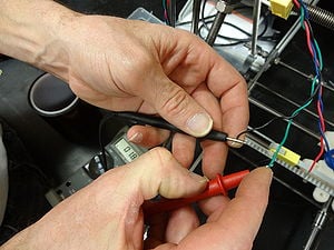
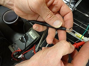
Motor wiring is terminal-specific. Use a multimeter to identify what motor leads belong together (pairs will have some low resistance, like 8 ohms whereas non-pairs will be essentially open circuits). The rest of the wiring is not terminal-specific, so you do not need to worry about polarity.
Once everything is wired up, check motor rotation and if it is wrong, swap conductor pairs.
Building it[edit | edit source]
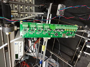
Screw the Melzi mounts onto the Melzi board with m3 screws, bolts and washers.
Mount the Melzi board to the right of your printer on the far side of the extruder using zip ties.
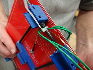
Solder the 3 feet of wire to the thermistor (orange). Solder 3 feet of wire to the front metal contact on the heated board. Zip tie the wires to the heated board to ensure you do not stress the soldered joints.
Solder extensions to any wires that are necessary to ensure they can reach to the Melzi without running into the moving parts. Then heat shrink tube over them to clean them up. Optional braid all your wires.
How do we know what wires are paired?
Get the multimeter and measure the leads on the steppers. Black and green are a pair as can be seen in the images.
Continue: MOST HS RepRap build 2


