
MOST RepRap Primer


| Hardware license | CERN-OHL-S |
|---|---|
| Certifications | Start OSHWA certification |
-
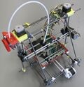 A MOST Mendel Prusa RepRap - Summer 2013 Version
 -
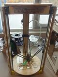 A MOST Delta RepRap - Summer 2014 Version -- recommended build <$500


The RepRap 3-D printer is a self REPlicating RAPid prototyper that uses a manufacturing method known as fused deposition modelling (FDM) to build physical objects from 3-D computer models. It is open source technology and so is accessible to everyone having an interest in it. Users and builders of open source technology become part of a global community and they are encouraged to tweak designs, reapply the technology and share their discoveries and innovations with that community.
Consumables - Electricity and Filament
[edit | edit source]The RepRap printer uses electricity and plastic filament to produce objects. The filament is similar to that used in weed whackers (in fact, some people have printed with weed whacker filament) and is typically made from ABS or PLA. The filament comes in coils or on spools and is typically sold by weight. Two different filament diameters are in common use, 1.75mm and 3mm.
Alphabet Soup: STLs, SCAD, g-code, oh my!
[edit | edit source]As with all digital technology, 3-D printing is awash in acronyms and jargon. This is not an exhaustive list, just a useful list of the most often used.
BOM
[edit | edit source]It's really not as scary as it sounds. A Bill Of Materials is simply a list of the parts required.
SCAD
[edit | edit source]A SCAD file is a file created in OpenSCAD, a software for creating solid 3D CAD (Computer-aided design) models. It is free software and available for Linux/UNIX, Windows and Mac OS X. OpenSCAD can export STL files for printing.
STL
[edit | edit source]An STL file (attributed to STereoLithography) is a file that describes a 3-D shape as a collection of conterminous facets (a bunch of connected triangles) and serves as the fundamental 3-D file from which prints are made.
g-code
[edit | edit source]G-code is an ASCII file that serves as the instruction set for a given print. It is essentially the map that leads to a printed object, telling the printer where and how fast to move the axes, what temperature to set the hot end and heated bed to and what to do when the print is complete. G-code is what the printer controller translates into action.
Slicing
[edit | edit source]Slicing is the process of translating a 3-D software model (an STL file) into g-code. The slicer (slicing software) does exactly what it sounds like it might; just like a slicer at the deli department, it takes a large 3-D shape described by an STL file and slices it into consecutive thin layers in the z-direction (vertically).
Printer Controller
[edit | edit source]The MOST printer uses the Melzi printer controller. The printer controller is the brains of the outfit. It turns g-code into action by managing stepper motors, keeping track of temperature of the extruder hot end and the heated build platform and notifies the user of status and errors. It relies upon a special kind of software referred to as "firmware". There are several different flavors of RepRap firmware available; the MOST printer uses Repetier. Firmware is written in a version of C++ designed to operate with the open source Arduino prototyping boards, on which the Melzi printer controller is based. The most accessible way to configure firmware is by using the Arduino Integrated Development Environment (IDE).
Arduino
[edit | edit source]The printer controller is built around an open source electronics platform known as Arduino. RepRap printers were made possible only upon the advent of the Arduino; we wouldn't be doing what we are if it weren't for this exceptional technology.
Arduino IDE
[edit | edit source]The Arduino IDE is software used for developing programs to run on Arduino and Arduino-based boards.
Firmware
[edit | edit source]Firmware is really software. It's a program that runs on the printer controller, translating g-code into action, dealing with inputs and providing feedback to the user. It's written in C++, so is human-readable, but can be daunting to the uninitiated. There is need to become familiar with limited parts of the firmware as there are regular upgrades and with greater experience with the printer, users will want to tweak their printer which really requires cracking open the firmware.
Extrusion
[edit | edit source]Extrusion is a process in which material is pushed through a die to form a continuous or semi-continuous shape having a cross section determined by the shape of the die. In the case of the RepRap printer, extrusion produces only a smaller diameter filament, but more importantly increases the temperature of the filament such that it fuses with filament deposited before it (hence FDM). The shape of the object produced by the printer is determined by the path of the extruder nozzle over the build platform.
Extruder
[edit | edit source]The MOST printer extruder is a Bowden cable -based extruder (Bowden extruder). The RepRap extruder is made up of two parts, a hot end and a cold end. The cold end is the extruder drive, where the room temperature filament is pinched between a textured roller and an idler and forced into the hot end. At the hot end, the filament is heated just prior to being extruded onto the build platform or object being printed. There are a number of different extruder component designs, the MOST Prusa printer is designed for 3mm filament and uses a Wade's drive; the MOST Delta is designed for 1.75mm filament and uses an Airtripper drive. Both use a J-head hot end with a 0.5mm nozzle.
Bowden Cable
[edit | edit source]A Bowden cable is a flexible cable constrained within a sheath (tube) such that the cable can move back and forth and can even be compressed to some extent since it is constrained from bending by the sheath. We use a Bowden cable to enable the extruder and the hot end to be separated. In this way only the actual hot end has to be moved over the printbed and the heavy extruder sits off on the side. This allows for faster printing.
Drive Gear
[edit | edit source]Hobbed Bolt The hobbed bolt is the textured part of the extruder drive. It has teeth cut into it that dig into the filament so that torque produced by a stepper motor is translated into linear motion in the filament. (Hobbing is a machining method commonly used to produce gears. All of the gears for the RepRap are printed instead.) The MOST Prusa uses a hobbed bolt in its Wade extruder.
Drive Gear A drive gear does the same thing as a hobbed bolt, it's just not a bolt. The mk7 drive gear is popular and usually what does the work in an Airtripper's Bowden extruder drive. The MOST Delta uses an Airtripper, including its mk7 drive gear.
Extruder Drive Idler
[edit | edit source]The untextured pinch wheel is referred to as an idler. In the case of the RepRap printer, it is typically a skate board bearing (608zz or equivalent). The idler is pressed against the drive gear by springs.
Hot End (or Hotend)
[edit | edit source]The hot end is comprised of a heater and a temperature sensor (thermistor) neatly bundled in a metallic melt zone. It is heated electrically and the temperature is carefully controlled and set based upon the material the filament being extruded is made of.
Nozzle
[edit | edit source]The nozzle is where the extruded filament exits the extruder. There are two common nozzle diameters, 0.5mm and 0.35mm. It is important to note that there is a relationship between nozzle diameter and optimal layer thickness.
MOST Prusa Motion Control
[edit | edit source]The MOST Prusa is based upon a Prusa Mendel, which is a gantry or Cartesian robot consisting of three linear axes, x, y and z each driven by individually controlled stepper motors. The x- and y-axes utilize timing belts and pulleys whereas the z-axis uses a pair of individually driven lead screws. The precise location of the axes is maintained by the printer controller (which also manages temperatures) and is based upon keeping track of the number of "steps" made by each motor after homing.
X-axis
[edit | edit source]The x-axis on the MOST Prusa is assembled around black plastic parts. It is suspended off the z-axis.
Y-axis
[edit | edit source]The y-axis on the MOST Prusa is assembled around white plastic parts. It is attached directly to the frame and home for the build platform.
Z-axis
[edit | edit source]The z-axis on the MOST Prusa is assembled around yellow plastic parts. This axis moves on lead screws controlled by a pair of stepper motors mounted at the top apex of the printer.
Stepper Motor
[edit | edit source]A stepper motor is an electric motor that only moves a fixed number of degrees at a time and so can be used for relatively precise motion control and positioning. The number of "steps" through a full rotation is determined by the design of the motor. The MOST printers use 200 step (1.8 degree) motors; 200 steps are required to make a full revolution of 360 degrees.
Micro Stepping
[edit | edit source]Stepper motors can be manipulated electrically to make fractional steps so that a 200 step motors can actually be made to do 800 or 1600 or even 3200 steps to make a complete revolution. This is referred to as microstepping and is employed by the printer controller to increase the resolution of the printer. The Melzi controller is set for 1/16 microstepping, so it does 3200 steps per revolution.
Limit switch (or End Stop)
[edit | edit source]A limit switch is a switch with an arm on it that gets bumped by something on the axis it is associated with indicating that the axis has reached its extreme position (home). Most controller software uses this position as the origin of the printable space.
Homing
[edit | edit source]Homing is the act of determining where the physical origins of each of the three axes are. It is done by moving each axis until a limit switch (end stop) is contacted. Those points are then essentially remembered by the printer controller, which keeps track of the number of steps clockwise and anticlockwise. Homing takes place before any print is started and is the key to motion control and positioning with the RepRap.
Timing Belt
[edit | edit source]A timing belt is basically a flexible gear. It is a belt with teeth molded into it and the belt "pitch" is the distance between the same point on neighboring teeth (akin to the period of a sinusoidal wave form). The MOST printer uses T5 timing belt; the center-to-center distance between neighboring teeth is 5mm.
Lead Screw and Captive Nut
[edit | edit source]A lead screw is just a threaded rod upon which a captive nut rides. The nut is restrained by the linear travelling member so that it doesn't rotate with the lead screw, hence it's "captive". There are four captive nuts on the MOST Prusa; one above and below both the x-axis idler and motor ends. Lead screws can be very precise, which is important in the z-axis since layer height is typically a small fraction of a millimeter.
Backlash
[edit | edit source]Backlash is the result of clearance between meshed parts, like gear-to-gear, pulley-to-timing belt or lead screw-to-captive nut. It isn't a significant issue with the MOST printer design but it is worth being aware of. The plastic gears on the extruder drive will wear, creating more backlash which will become manifest upon retraction of filament; with time an increasing amount of movement will be consumed in compensating for increasing backlash - less filament will be retracted. Backlash is a really big deal where high precision is necessary, like in the z-axis. Fortunately, gravity and a little spring saves the day; the x-axis is always pushed down on the lower captive nut effectively eliminating backlash.
Bearings
[edit | edit source]Two types of bearings are used on the MOST printer. One is a rotary bearing called a 608zz, an inexpensive skateboard bearing, and the other is a linear bearing called a LM8UU. The bearing identifiers (608 and LM8UU) are used colloquially when discussing printers.
Steps per Millimeter
[edit | edit source]All the moving done by the printer is accomplished by stepping the motors such that they rotate some amount. That rotation is translated to linear motion by 1) a timing belt and pulley, 2) a lead screw and captive nut, or 3) a pinch roller and filament.
In the case of timing belts, rotation of the pulley passes some number of belt teeth over the pulley cogs. The MOST printers use 12 tooth pulleys, so one complete revolution yields linear motion of 60mm (12 teeth × 5mm/tooth). Since the motors are 200 steps/revolution and the Melzi employs 1/16 microstepping a total of 53.333 steps are required to move the timing belt 1mm ((200 steps/rev × 16 microsteps/step) / 60mm).
Lead screws are pretty much the same except the thread pitch is used. M8 threaded rod has a pitch of 1.25mm, 3200 steps are required to make a complete revolution (200 steps/rev x 16 microsteps/step) so 2560 steps are required to move a captive nut 1mm along the threaded rod (3200 steps/rev / 1.25mm/rev).
Pinch rollers should behave just like gears, so one should be able to calculate steps/mm of filament movement if the geared extruder drive and the pinch roller was treated as if it were a transmission. However, the textured roller interacts differently with different filament materials and even color changes in the same material can result in different behavior in the extruder system (resulting from back pressure on the extruder drive, softness of the material and probably other interesting phenomena). In practice, the steps per millimeter of filament is determined empirically by measuring the amount of filament actually extruded and factoring steps by the ratio of expected movement to actual movement. This isn't something to get excited over; there are many ways to manipulate extrusion rate and ultimately what matters is that the print produced is dimensionally sound and aesthetically acceptable.
All of this matters because the firmware uses these key bits of information to move all the axes just the right amount. If these values are wrong, the printer won't produce a print matching the dimensions of the model and probably won't even produce a usable print (keep in mind that the slicer figures all the movements out based on volume of filament required to fill intervening space). Printer users must set these values in firmware and the terms "steps per millimeter" and "E steps per millimeter" are frequently bandied about. The first term refers to the three linear axes and the latter refers to the extruder (E = extruder).
MOST Delta Motion Control
[edit | edit source]Pretty much everything stated above for the MOST Prusa holds true for the MOST Delta printer except that the kinematics are vastly different. Whereas the Cartesian printer design uses a single motor to move a single axis linearly, the delta printer simultaneously moves all of motors to position the end effector. Instead of having a right rectangular prismatic build volume, the delta has a roughly cylindrical build volume.
Axes?
[edit | edit source]The delta doesn't really have axes (x, y, z), so the three linear motion control portions of the printer are referred to as "towers" or "apexes". It's still important to uniquely identify the apexes since each has a motor and an associated limit switch and the order in which all of these are wired to the controller board matters. All of the controller boards are designed for Cartesian printers, their motor and limit switch terminals are labelled "x", "y" and "z", so it's only logical to identify the apexes to match. If during commissioning of the printer you notice that the print is mirrored (for instance print is legible when its reflection is viewed) the reason is probably that the x and y towers are reversed on the controller. Swap the x and y motor leads and their respective limit switch leads and the printer should print correctly. (Warning: never connect or disconnect motor wires while the power is on!)
Calibration
[edit | edit source]Whereas calibration of a Cartesian printer requires only knowledge of the belt pitch, number of teeth on the pulley and steps to complete a revolution of the pulley, delta printers require additional data to ensure that prints are produced to scale and the end effector moves in the x-y plane while printing. The distance between the tie rod pivot points and the effective radius of the printer must also be accurately known. It is also extremely important that care is taken during assembly of the printer to ensure that the apexes are equally spaced and the lengths of the tie rods are identical and carefully measured. One additional requirement is that the carriages all engage their respective limit switches in a plane parallel to the build platform. This is done by setting the height of the limit switch adjustment screws on each of the carriages.
Delta printer kinematics are less intuitive than that used by Cartesian printers and calibrating them can be challenging, but there are payoffs. Delta's have significantly larger build envelopes in a similarly sized footprint, and once calibrated typically require less twiddling to keep going. The MOST Delta design is very robust and tolerates transporting much better than does the Prusa design. Deltas are also much easier to build and have fewer parts, so they're cheaper, too. Finally, the design is easily adapted to different purpose, making it very flexible.
Miscellany
[edit | edit source]Heated Build Platform
[edit | edit source]The heated build platform is a circuit board that does nothing but produce heat. Heat helps the initial layer to stick to the build surface and helps reduce warping of the part during printing. This isn't strictly required and greatly increases the requirements on the power supply. The MOST Prusa has a heated build platform; the MOST Delta does not (but it can be added easily, if the power supply is also changed).
M2, M2.5, M3 - What's it all about?
[edit | edit source]The RepRap is built with metric screws, which aren't as common in the US as in other parts of the world. Metric screws have a pretty simple naming convention - M followed by a number representing the diameter of the screw followed by the length of the screw. M2 is a 2mm diameter standard thread screw; M2×10 is a 2mm diameter screw 10mm long below the cap.
Printing Jargon
[edit | edit source]Retraction
[edit | edit source]Retraction is simply backing the filament out of the extruder. It is necessary when moving from one print point to the next when no filament should be extruded, like between adjacent printed parts. The Bowden design stores energy in compressed filament between the drive and hot end and tension in the Bowden sheath. Additional energy is supplied by a change in density upon heating the filament in the hot end. Between these (and probably other fascinating phenomena) there is a tendency for plastic to ooze out of the nozzle even after stopping the extruder drive. The amount of oozed material is minimized by backing filament out of the hot end; the extruder drive is put in reverse. The amount of filament retracted is set during the slicing operation.
Over or Under Extrusion
[edit | edit source]The slicer does all the math to figure out the volume of plastic to extrude per length of extruder nozzle distance travelled. It's all volumetric, but it's expressed in g-code in linear distance (mm of filament), hence the importance of getting E steps reasonably accurate in firmware. Ultimately, though, the extrusion rate changes and the user must tweak settings to produce a good print.
Over extruding is a condition in which too much filament is extruded. It's revealed by the presence of bumpy vertical sides, bulbous prints and the nozzle grinding over the top of the print due to insufficient clearance. A quick way to assess minor over extrusion is to rub a finger over solid infill layers at the top of the print and note how smooth it feels. If it has a shark skin-like feeling (rougher in one direction) then the extrusion rate is too high. If it's smooth then the extrusion rate is just right or too low.
Under extruding is the opposite condition - too little filament is being extruded. It manifests itself by extrudate tearing during long partial infill runs in the interior of the print and holes or gaps in solid infill layers. Feeling partial infill layers with a fingertip is useful for diagnosing - if the print feels sharp, then tearing is taking place.
Don't make assessments of extrusion rates based on the first few layers or on a single solid infill layer. Patience pays off; watch the printer and assess at various points during the print.
Underextrusion can be caused by more than just incorrect settings: there may be something blocking the nozzle, or the temperature may be too low to melt the filament enough. In such cases, the extruder drive will be unable to push the filament through the nozzle at the speed it is instructed to. This is noticeable as a clicking noise from the filament skipping in the extruder, or in more serious cases a grinding noise. When putting two fingers on the filament at the extruder infeed, it is also obvious when the filament is or is not moving.
| Authors | |
|---|---|
| License | CC-BY-SA-3.0 |
| Cite as | Gcanzalo, Wijnen (2013–2026). "MOST RepRap Primer". Appropedia. Retrieved July 24, 2026. |