Linking board mounting screws are located in difficult-to-reach locations and pilot holes greatly simplify assembly of the motor and idler ends. Pilot holes may be drilled in other wooden structural components and those will be treated in their respective assembly steps.
To minimize swelling and shrinking due to changes in humidity, sealing the plywood is recommended.
There are two linking board pilot hole jigs for accurately locating the positions of pilot holes. One each for the left and right sides of the boards. Ream the holes in the triangular pattern with a 3mm (1/8") drill bit.
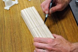
Marking one edge of the boards.Stack the linking boards so that their edges are up and mark that edge with a pencil.
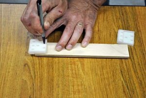
Marking linking board pilot hole locations.Place one of the pilot hole jigs on the end of a board with the marked edge of the board on the same side as the narrow stop at the bottom of the jig. Push the board firmly into the jig and with a sharp pencil, mark the location of the pilot holes. Repeat with the other jig on the opposite end of the board ensuring that the marked edge is towards the bottom of the jig.
Repeat with the remaining linking boards.
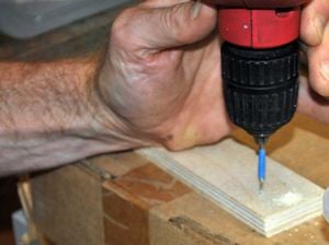
Drilling linking board pilot holes.Drill 2mm (1/16") pilot holes at the marked positions on each board being careful to not drill all the way through the board.


