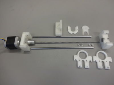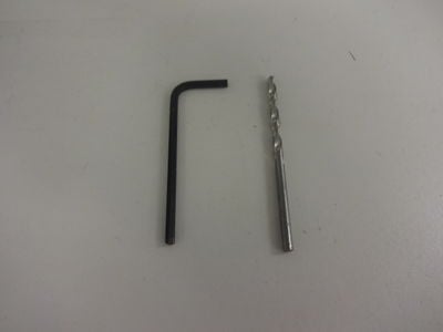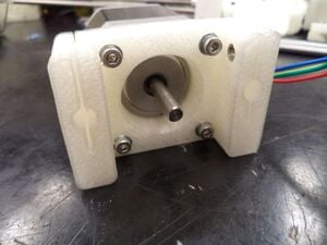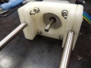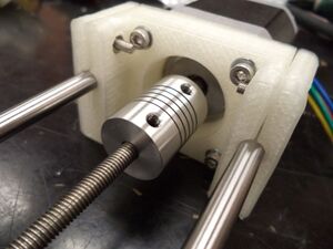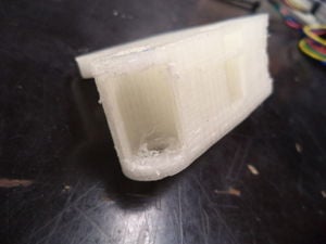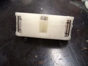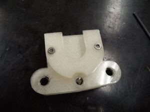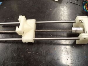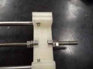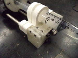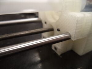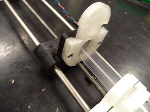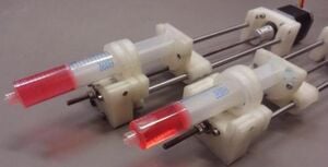
This article explores a new open-source method for developing and manufacturing high-quality scientific equipment suitable for use in virtually any laboratory. A syringe pump was designed using freely available open-source computer aided design (CAD) software and manufactured using an open-source RepRap 3-D printer and readily available parts. The design, bill of materials and assembly instructions are globally available to anyone wishing to use them. Details are provided covering the use of the CAD software and the RepRap 3-D printer. The use of a (partly open-source) Raspberry Pi computer as a wireless control device is also illustrated. Performance of the syringe pump was assessed and the methods used for assessment are detailed. The cost of the entire system, including the controller and web-based control interface, is on the order of 5% or less than one would expect to pay for a commercial syringe pump having similar performance. The design should suit the needs of a given research activity requiring a syringe pump including carefully controlled dosing of reagents, pharmaceuticals, and delivery of viscous 3-D printer media among other applications.
- The source code for the linear actuator and pump server are housed here: https://github.com/mtu-most/linear-actuator
- If you are customizing your own pump you will need MOST SCAD library files found here: https://github.com/mtu-most/most-scad-libraries Download them all and put them in the same folder as the files for the pump -- then the SCAD will compile correctly.
- For example STL files see https://www.youmagine.com/designs/syringe-pump
- See also: Lynch open source syringe pump modifications - includes 1) Escape mechanism to move pusher block without running the motor, 2)Open syringe clamp to allow easy removal, 3) Arduino Control with EasyDriver.
- To calculate the value of doing work on projects like this see:Quantifying the Value of Open Source Hardware Development
Materials and Tools[edit | edit source]
How to Build an Open-source Syringe Pump[edit | edit source]
Controller: Connection and Calibration[edit | edit source]
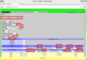
This is a description for using Franklin to control the device. Latest version available for free Github.
(The paper describes the electronics as it was originally implemented. This method is no longer maintained. It is now recommended to use a RepRap 3-D printer controller such as a RAMPS or Melzi, which you can pick up online and Franklin to control the device. The original instructions are available in the Discussion tab.)
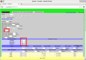
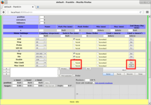
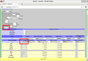
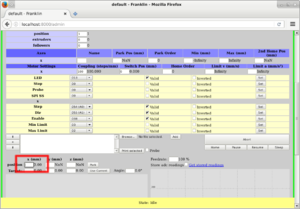
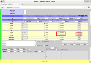
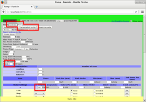
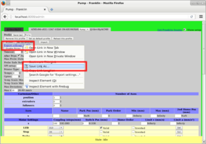
The motor must be connected to the control board on the terminals that are intended for the first axis (normally called X). In Franklin, load the profile for the board you have, then set up the profile and calibrate the pump:
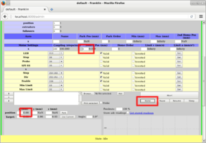
Pull the syringe out slightly past a big marker. Then using tiny steps, push the syringe to the bigger marker so the plunger is exactly on the mark. (Because of backlash, you want to do the entire procedure with pushing only.)
Click the home button to set the position to 0.
Push it further until you reach another marker (larger distance is better). Make sure to do small steps at the end, in order to make sure you do it by pushing only.
Record the current position.
Divide the reported number of mm times the coupling by the number of milliliters between the markers. This is the correct Coupling value for this syringe.
The pump is now ready to use. You can use the x position entry to move it manually, or upload G-Code which moves the X coordinate to move it in a pre-programmed pattern. A simple G-Code example is:
G91 ; Use relative positioning.
G1 X10 F600 ; Push 10 mL at 600 mL/min (10 mL/s).
G1 X1 F120 ; Push 1 mL at 100 mL/min (2 mL/s).
G4 P500 ; Wait 500 ms.
G1 X1 ; Push another mL at the same speed.
G1 X10 F600 ; Repeat.
G1 X1 F120
G0 X-5 ; Pull back 5 mL at maximum speed.
Minimum Pump Rate[edit | edit source]
The minimum pump amount is a single step of the motor; how much that is depends on the size of the syringe. Here the lead screw has a pitch of 0.8mm and the motor does 3200 microsteps per revolution, so one step is a plunger movement of 0.8mm/3200=250nm. The cross section of a 25ml syringe is around 4cm², so one step is the product of those, which is 0.1mm³=0.1μL.
There is no minimum value for the speed that the pump can go, but if you get near the step size, the flow will be in noticeable steps instead of continuous. For example, if you want 1μL/min, it will do one step every 6 seconds.
See also[edit | edit source]
- Lynch open source syringe pump modifications - includes 1) Escape mechanism to move pusher block without running the motor, 2)Open syringe clamp to allow easy removal, 3) Arduino Control with EasyDriver
- Open-source Lab
- Building research equipment with free, open-source hardware
- Open source science
- Open source optics
- Open source 3-D printing of OSAT
- Open-source hardware
- Syringe pump literature review
- Open Source 3-D Printed Nutating Mixer
- 3-D printable open source dual axis gimbal system for optoelectronic measurements
- Ystruder: open source multifunction extruder with sensing and monitoring capabilities
- Open Source Digitally Replicable Lab-Grade Scales
- Open Source Vacuum Oven Design for Low-Temperature Drying: Performance Evaluation for Recycled PET and Biomass
- Open Source 3-D Printed ISO 8655 Compliant Multichannel Pipette
- Open Source Scientific Bottle Roller
- Open Source Cold and Hot Scientific Sheet Press for Investigating Polymer-Based Material Properties
Coupled Initiatives[edit | edit source]
- Modified Open Source Syringe Pump Parts - by Dylan Lynch
- Open pump -Help to make better devices for healthcare and lab environments
- Open Syringe Pump on Hackaday by naroom - Arduino controlled
- Will Patrick's OS syringe pump at MIT
- Hedron Paste Extruder Project
- Trial database uploads:
- Universal paste extruder
- Bricoleur Clay Extruder, Open Source
- E-steps-per-mm method - Method for calculating the E-Steps-per-mm of an extruder based on the Open Source Syringe Pump.
- LVESPmm - Python script with GUI for calculating the E-Steps-per-mm of an extruder based on the Open Source Syringe Pump.
In the News[edit | edit source]
- Science Just Got Cheaper (and Faster): Design Library Lets Researchers Print their Own Syringe Pumps - Michigan Tech News
- Doctors Could 3D Print Their Own Tools For a Fraction of the Cost - Gizmodo, Gizmodo India, Gizmodo Australia, USA News
- 3D Printed Syringe Pumps are Perfect for Cash Strapped Scientists - Motherboard
- 3D Printable Syringe Pump Design Lowers Lab Costs - Med Device
- 3D-printed syringe pumps could cut the cost of scientific research - Gizmag
- 3-D printing leads to another advance in make-it-yourself lab equipment - Phys.org
- Make-it-yourself lab equipment with 3-D printing- Nanowerk
- 3D-printed syringe pumps could cut a cost of systematic research- World News Source
- Researchers could now 3D print their own syringe pumps using a RepRap - 3Ders
- Doing science just got cheaper -- and faster - Science Codex
- RepRap: Open Source Lab Equipment Makes Science Cheaper - And Faster - Science 2.0
- 3D Printed Syringe Pumps Cost a Mere Fraction of Traditional Pumps - 3D Print
- "Another day, another phenomenal addition to the list of practical, hype-less, real, tangible, 3D printable tools that are bound to bring on some welcome changes. This time, it's the scientific community that can sing praises and raise their glasses as they're about to reap the benefits – and save a bundle – on 3D printed syringe pumps."
- Doing science just got cheaper -- and faster - ECN
- Doctors Can 3D Print Syringe Pumps for a Pittance Now - Softpedia
- 3DP Leads to Another Advance in DIY Science Equipment - Engineering.com
- The medical world could become much cheaper thanks to 3D printing Inside 3DP
- 3D-printed syringe pumps could cut the cost of scientific research -- Electronic Engineering Journal
- Michigan Tech Offers Free Designs For 3D Printing Lab Gear - Technology Century
- 3D-Printed Lab Equipment Stretches Research Budgets- Polymer Solutions Newsblog, Lab Manager
- New open source designs make lab work affordable - The Lode
- Science just got cheaper (and faster) - Today's Medical Developments
- Open-Source Syringe Pump Library - Replicator World
- Open source syringe pump - Raspberrypi.org
- Open-Source Syringe Pump #piday #raspberrypi @Raspberry_Pi - Adafruit
- Open source syringe pump - FreeIO.org
- How 3D Printing Can Reduce Medical Expenses - Nation Swell
- A TEMPLATE LIBRARY ALLOWS RESEARCHERS TO PRINT IN 3D, THEIR OWN SYRINGE PUMPS - InfoHighTech (France)
- Open Source Hardware soll durch Kosteneinsparung Medizin revolutionieren - 3Druck (Germany)
- 3D printed syringe pump - What Next (Poland)
- Injection pump open source 3D printing model library to help scientists provincial money - Maker8 (China)
- 3D打印,模型库,注射泵,开源 - 中关村在线办公打印频道 - oa.zol.com.cn (Zhongguancun Online (zol.com.cn) - the world's first Chinese technology portal, Greater China's most commercially valuable IT professional portal.)
- Científicos ahorran millones en equipo con simple invento - Electronics Online (Spanish)
- 3D Printed Open Hardware Syringe Yields $800M Value, Study Finds- 3D Printing Industry
- 'Open-hardware' pioneers push for low-cost lab kit -Nature News


