
Hotel Perote solar pool heating system

| Type | Solar hot water system |
|---|---|
| Authors | Aaron Antrim Tybie Matt |
| Location | Parras, Mexico |
| Status | Deployed |
| Years | 2006 |
| Made | Yes |
| Replicated | No |

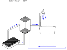
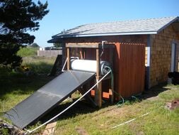
A passive solar heating system was designed, built and installed on the roof of Hotel Perote in Parras de la Fuente to heat the hotel's pool. This design utilizes PVC and copper piping to heat the pool water to 28 degrees centigrade from October to March.
Parras de la Fuente is a desert oasis town of about 44,000 residents located in the south of the Mexican state of Coahuila. Along with textile manufacturing, tourism is one of the main industries in Parras. Tourism has become increasingly emphasized after Parras's designation as the "primer pueblo mágico del Norte de México." Parras is warm in the summer, and cooler in the winter, but temperatures rarely fall below freezing, snow falls once every several years.
- Elevation
- 1,505 m
- Longitude
- 102°11' W
- Latitude
- 25°30' N
Hotel Perote
[edit | edit source]Antiqua Hacienda de Perote is a hotel, restaurant, nuez (pecan) ranch, vineyard, and winery. It sits on about 500 acres on the western-most edge of Parras. According to Igancio (Nacho) Chacon, Perote's owner, Perote's hotel business has been growing rapidly, and in 2006, the hotel was constructing rooms to meet demand.
Contacting Hotel Perote
[edit | edit source]- Visit Hotel Perote's in-town office, near UTC Parras
- Ramos Arizpe # 131 Col. Centro C.P. 27980
- Parras de la Fuente, Coahuila
- Call the Hotel Perote in-town office (see Phone Calls section of Parras Handbook)
- (842) 422 1698
- Fax
- (842) 422 0698
- Call Lic. Ignacio Chacon's (owner's) mobile phone
- Email Aaron Antrim to get this phone number
- Website
- Antiqua Hacienda de Perote
Visiting Hotel Perote
[edit | edit source]Go a few kilometers west on Calle Madero, the street in front of UTC Parras, passing turns for Estanque de la Luz and La Illusion. Consult this map from the Hotel Perote website for additional directions. A cab to Perote from UTC will cost 50 pesos. See the Taxis section of the Parras Handbook for more information.
2005 History
[edit | edit source]Parras Program students Heather Kuoppamaki and Rowan Steele built a rooftop solar hot water system for Hotel Perote in the summer of 2005. Intended as prototype for a larger system to heat a spring-fed swimming pool (alberca), then being constructed, the system was sized to provide heated water for a single hotel bathroom. For more information on the 2005 system, consult Heather and Rowan's File:2005Perotepaper.doc. The 2005 system is no longer located at Perote, and has been moved to the residence of someone afiliated with the local city government. For more on the whereabouts of this system, contact Ignacio Chacon.
2006 Project
[edit | edit source]Required system performance
[edit | edit source]Igancio has requested a system to keep the pool at 28° centigrade from October to March. The design problem revolves on this performance parameter and several state variables.
Existing site, equipment, and state variables
[edit | edit source]Pool dimensions
[edit | edit source]
- Pool surface area
- (Necessary for considering heat loss)
- (11.2 by 6.7 meters)+(1.82*pi) = 85 square meters
- Pool volume
- The total volume of the pool is approx 112 cubic meters, or 112,000 liters.
Installation site dimensions
[edit | edit source]- Roof dimensions
- 77 ft by 31 feet
- Roof height from deck
- 26 feet
Pump specifications
[edit | edit source]-
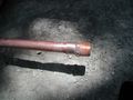
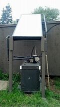
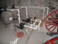 Figure 1: Currently, water is pumped through a sand filtration system.
 -
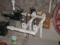 Figure 2: Close up of water flow valves.
 -
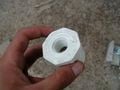
 Figure 3: Pump label. No additional flow rate information could be found from the information on this label.


The Solar Collector
[edit | edit source] |
The solar collector design calls for 30 three meter lengths of half inch diameter copper pipe run in parallel between two one and a half inch diameter PVC ends. Currently, however, only 20 lengths of copper tube have been installed. The system, however, is easily expandable, and additional copper pieces can be installed by cutting the caps off the ending PVC nipples to add additional T's and reducers.
The lengths of half inch copper pipe are connected to the one and a half inch PVC pipe by PVC "T's". For easy testing, the system design requests a spigot for obtaining water temperature readings at a point after the water has passed through the collector, however this feature has not yet been implemented. A thermometer could also be installed in the pool. |
Construction
[edit | edit source]-
 Side view of Perote installation site with pump area below the deck.
 -
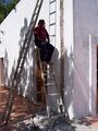 Cutting hole in Adobe wall to run PVC pipe to rooftop collector.
 -
 Threaded ends slide on copper pipe.
 -
 Close-up: threaded end on copper pipe..
 -
 Soldering copper threaded ends on copper pipes.
 -
 One-and-a-half to one-half inch PVC reducer.
 -
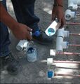 Installing T's on the PVC reducers.
 -
 Connecting T's together with nipples (approx 4 inch sections of PVC tube).
 -
 One side of T's attached in line with nipples.
 -
 System on roof with Hotel Perote staff. On left, Ramón and Manuel.
 -
 System on roof with Perote staff and Aaron Antrim, student project team member.
 -
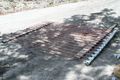
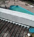 Collector on roof with view of alberca (pool) below.


Connection to existing pool plumbing
[edit | edit source]
The 2006 project team's design calls for the new rooftop solar collector to be connected to the pipe returning water to the pool after it has passed through the sand filter. Heating water after it has been filtered will prevent debris from clogging the solar hot water heating system. A gate valve can be closed to force water through the solar collector. When open, water will return directly from the filters to the pool without passing through the solar collector.
The pipes to the rooftop solar collector will share identical specifications with the existing pipes running to and from the pool: one and a half inch diameter "schedule 40" PVC. Schedule 40 PVC tubing is thicker than conventional PVC, and is used in pool systems. The additional thickness and strength of schedule 40 PVC will provide improved water pressure tolerance and improved heat and solar radiation tolerance, which will be important, as these PVC pipes will be carrying heated water, and will be exposed to heat and solar radiation on the roof.
The piping delivering and returning water from the rooftop system will first run directly up to the ceiling of the pump room from where it is connected to filter outflow. It will run along the ceiling to the point where it must pass through the concrete floor of the deck above to run 6 meters to the roof.
[calculate head loss for pipes running up to the roof]
Operation
[edit | edit source]- The main flow control valve (see valve setup diagram, fig. 6) should be opened to allow the water to pass directly to the pool when temperatures may drop below freezing, in order to prevent the pipes from bursting.
- The collector is only effective when filter pumps pass water through it. Therefore, filter pumps should be run during peak sun hours.
- Covering the pool at night will increase heat retention.
Effectiveness of Solar Collector for Perote
[edit | edit source]The sizing of the collector for the pool system is difficult to determine. In order to maintain the pool's temperature throughout the winter it is necessary to determine the energy loss of the pool during that time, something that is difficult to do in July. The system was designed based on the available supply of copper pipe, if this proves to be inadequate the system was constructed in such a way that it is easy to expand and therefore increase the detention time in the collector. At the first meeting at Hotel Perote 100 meters of half-inch copper pipe was made available for this project. This gives the collector a volume of 50.6 liters. The manual for the pumps was not available, and it was not possible to measure the flow before construction, so a estimate of 114 L/m was used for the flow rate. This flow rate was based on US pump sizing standards for the pool volume. Based on the collector volume and flow rate the hydraulic retention time is:
T = V/Q = (50.6 L)/(114 L/m) = 0.44 m
Unfortunately this retention time is rather small and the testes conducted with the copper pipe may not be accurate at this range. The water temperature in the test pipe gained about two degrees (C) per minute for the first couple of minutes in direct sun. Based on that data it was estimated than in the first half minute the temperature will increase one degree. The volume of water being heated was based on the flow rate and the equivalent of a minimum of 4.5 hours direct sun in the winter:
V = T*Q = (4.5 hr * 60 m / 1 hr) * (114 L/m) = 30780 L
To determine the energy added the volume is changed to mass using a density of 1 L/kg, which means that 30780 kg of water is heated 1°C.
Q = mswT
- Q = heat transfer
- m = mass of water
- sw = specific heat of water
- ΔT = change in temperature
Q =(30780 kg)(4.186 kJ/kg* C)(1°C) => Q = 128845 kJ ≈ 129 MJ
The addition of 129 MJ per day seems large, however when considering the volume of the pool the effect may not be substantial. The only way to know whether the 129 MJ is enough is to monitor the pool temperature over the course of a year. If more heat needs to be added the collector volume can be increased without much difficulty.
Tybie Fitzhugh
[edit | edit source]31 January 2007
When I first arrived, the system was not set up. I asked why, and a technician told me that it was because they did not have a copy of the plans to connect it. Later Ignacio told me that they had needed to change the plans because the system needed an extra ¾ horsepower pump in order to function. He said they had the pump, they knew how to connect it, but that they had been waiting because someone had instructed them to wait until we, the HSU team, gave the new plan the okay. He did not say who it was who had told him that. Later another technician told me that they could not connect the pump because they did not have the plans. I printed a copy of the plans from Appropedia and with Pablo's help, translated it into Spanish and presented the technicians with both the handwritten Spanish translation of the plans and the original English version printed from Appropedia. I tried to talk with the technicians about where to put the extra pump, but that day they seemed to already know where they wanted it. I went up on the roof and took pictures of the pipes – there are still the original 20 lengths of copper tubing.
They actually connected the system, with the extra ¾ horsepower pump, the day before I had to leave. They had told me a few days earlier that I would be able to come and test it. I arrived with the Hobo, but when I went to the basement nothing was running. I asked the technicians if we could test the system and they said they were going to wait to use the system until there was warmer weather. This seemed strange, but they were firm on their decision. There were very few guests staying at Perote. I think in the whole time I saw only three families, all on different days. Most of the time there was no one to be found anywhere in the offices, they seemed low staffed. It definitely seemed off season for business. Most of the time they kept the pumps shut off, and the pool was often dirty. --Tybie
Temperature readings
[edit | edit source]Tybie made readings using a Hobo Data Logger, kindly provided by Lonny.
Note: The logger must be started and stopped by a computer. Since I could not connect the logger to my laptop, Pablo and I started it and stopped it at Pablo's house using his desktop computer. Therefore it was necessary to have the logger running in my backpack for the trip to Hotel Perote and the trip back. This explains for the sudden jolts in temperature at the beginning and end of the logs.
The Hobo Logger has outlets for 4 probes; however, only 3 were connected and activated for testing. Probes 1 and 2 measured ambient air temperature while Probe 3 measured water temperature. In the data logs below each probe has two columns. The first measures degrees Fahrenheit while the second measures degres Celcius. Thus (*F)(*1) is the Fahrenheit column for Probe 1, and so forth. --Tybie
Recommendations for 2007 Team
[edit | edit source]- Install spigot on the roof to test collector performance.
- Add additional copper pipe if more heating performance is necessary.
- Create informational placard to inform guests about the solar hot water system.
2007 Team Update
[edit | edit source]A number of issues prevented our team from making forward progress on the system itself this summer. We did however make progress in identifying the problems and examining other options for Ignacio and Hotel Perote.
Problems/Issues
[edit | edit source]- Upon examining the system pump and plumbing connections to the pool filtration system, it became obvious that the system was not linked to the pool system as designed by the previous teams. The pump for the solar system is drawing water from the plumbing before it goes through the filtration system. This is bad for the following reasons:
- The pump pushing water to the solar system is not a pool pump and does not have a course filter to keep out large objects such as jewelery or other pool originated objects. This could easily destroy the pump;
- the small pipes of the solar system are designed for clean water and could become clogged if dirt and debris make their way to the system.
- By bypassing the filter system, our system returns dirty water to the pool which defeats the integrity of the filter system, and ultimately it purpose.
- The pump that was installed to force the water to the solar collector is only strong enough to function for about ten minutes. It quickly becomes overworked and shuts off.
- The collector itself needs a lot of work as well. Here are the issues we found with the collector.
- Our research has informed us that chlorine is corrosive in its interaction with copper and thus for systems that utilize copper a heat exchanger (closed-loop) system or a chlorine alternative are strongly recommended.
- The solar collector is much to small for the desired function. When we tested the system, the water moved through the copper pipes much too quickly to absorb any substantial amount of heat.
- The actual design of the collector may not be the most appropriate for the given situation. The copper was used by the previous team because it was available at the time, but in order for the system to be at a suitable size to heat the pool, it must be much bigger and copper is very expensive too source locally.
- The insulation of the system as a whole is very poor. The collector itself needs insulation underneath it to prevent the transfer of heat to the cement roof. The pipes that transfer the water to and from the roof also have a high potential to transfer heat into the walls and should be insulated to maximize efficiency.
Potential Solutions
[edit | edit source]- We invited a local plumber/pump salesman to come out and examine the system. His recommendations where useful to help us design a plumbing configuration that utilizes filtered water. This would solve a number of problems associated with the current system configuration.
- The solar collector system would be in line with the filter pumps and could use the power of them to pump the water to the collector, thus eliminating the need for the small, underpowered pump.
- The issues with the unfiltered water clogging the system and returning to the pool would be eliminated.
- As far as the collector itself is concerned, we tried to take a step back and look at this project as a whole. We tried to determine the most appropriate approach to heating the pool. After further examination of the available materials in Parras and the efficiency of the current system, Ignacio is now looking for a commercially manufactured collector to increase efficiency and hopefully keep costs to a minimum. This appears to be the most appropriate approach at this point and helping Ignacio determine what an appropriate system would look like became our priority.
Excel Programs
[edit | edit source]Below are links to semi-completed Excel worksheets from RETScreen. This extensive program helps size systems according to the collector type. Each link corresponds to the specific systems we entered into the program. We included Evacuated Tube Collectors, Polypropylene/Unglazed Collectors, Glazed/Flat Plate Collectors, as well as an analysis of the current system. The designers of the Excel program included a PDF document to facilitate the understanding and use of the program. We have included this document as well. The current system analysis may not be as accurate as the others as the program is designed for a more standardized/commercial collector. The figures on the costs pages were the hardest to determine and may vary from location to location. We had trouble finding costs of systems in Mexico, so 20% was added to the price of collectors found in the United States as a shipping/importation estimate.
Evacuated Tube Collector
[edit | edit source]Polypropylene/Unglazed Collector
[edit | edit source]Current Perote System
[edit | edit source]More Discussion
[edit | edit source]See the talk page for more information and conversation about this project.
Related projects
[edit | edit source]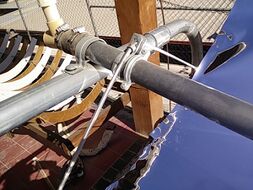
External links
[edit | edit source]"Water Heater Efficiency" [1]
"Energy From Natural Gas" [2]
Suggested links for the 2007 team
[edit | edit source]- Start with these basics. Notice the other link to this same site listed below that adresses system sizing.
- http://www.eere.energy.gov/consumer/your_home/water_heating/index.cfm/mytopic=13230
- Solar hot water basics from Australia Gov, UK Gov (44 pages) and private industry.
- http://web.archive.org/web/20071030020346/http://www.greenhouse.gov.au:80/yourhome/technical/fs43.htm
- http://www.greenspec.co.uk/documents/energy/EST-solarWaterHeating.pdf
- http://web.archive.org/web/20090217223120/http://azsolarcenter.com:80/technology/solarh20.html
- Some info on solar swimming pools, but it suggests using the pool´s filter pumps which may not work in your case (but are we sure?).
- http://web.archive.org/web/20080522130308/http://www.southface.org/web/resources%26services/publications/factsheets/residential_solar_water111804.pdf
- Sizing a Solar Swimming Pool Heating System.
- http://www.eere.energy.gov/consumer/your_home/water_heating/index.cfm/mytopic=13250
- Good narrative on sizing pumps. Nothing about solar, but some good pointers. It is missing images.
- http://pooluniversity.org/choosing-the-right-pump-for-the-job/
- Some pool pump sizing information.
- http://web.archive.org/web/20141213132200/http://www.poolplaza.com:80/pool-pump-sizing-2.shtml
- Nice pump curves (page 36).
- http://web.archive.org/web/20110626021732/http://www.siemens.com.mx:80/A&D/Data/Cat_motores_Siemens.pdf
- How to read a pump table (please note that this is from an irrigation pump, but the table style still applies).
- http://web.archive.org/web/20111127043149/http://www.johndeerelandscapes.com:80/_Products/Irrg_curve.asp
| Authors | |
|---|---|
| License | CC-BY-SA-3.0 |
| Organizations | Parras 2006, Parras 2007, Cal Poly Humboldt |
| Cite as | Canadienito, Aaron, Tybie, Climbingsurfer, Lonny, Mcm781 (2006–2026). "Hotel Perote solar pool heating system". Appropedia. Retrieved July 16, 2026. |