

Introduction[edit | edit source]
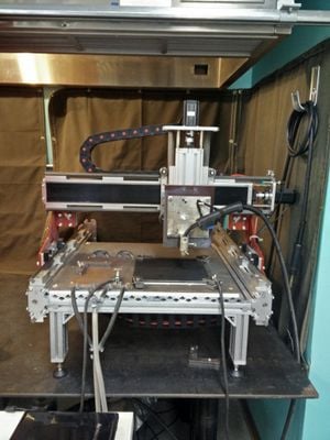
CNC Router Parts already has a capable of 3D motion directed by a control unit (See Figure 1). In order to add metal 3D printing functionality, a weld gun or a spool gun need to be mounted in place of a milling tool. The weld gun is acting as a printer head that deposits filament which is a weld wire on a substrate that mounted on the base of the CNC Router Parts. The control unit also need to be able to send output signal to control the welder.
From a 3D model, a slicer open-source software for metal 3D printing, MOST_Metal_Cura, can be used to slice the model into layers and generates a numerical control programming language, G-Code, file which is a planning of movements in each layer in order to fill all the layers with filament.
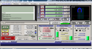
On a computer connected to the control unit through Ethernet cable, a client software called Mach3 which accepts a G-Code file and then interprets those G-Code line by line and communicates with the control unit to regulate the 3D movements.
As the movement happens, the wire is welding bead by bead and layer by layer until it fulfill the model.
- This will work with any kit cnc router. The one we have is Benchtop PRO CNC Machine, https://www.cncrouterparts.com/benchtop-pro-cnc-machine-kit-p-314.html
- Full source code for voltage and current data processing available at: MOST-Voltage-Current-Data-Processor (*.m for MATLAB or Octave)
- 3D Metal Printing Slicer Plugin
- Franklin firmware -- for a complete guide on how to set this up see: Using Franklin on a CNC Router Parts 3-D printer
- Last version: Integrated Voltage—Current Monitoring and Control of Gas Metal Arc Weld Magnetic Ball-Jointed Open Source 3-D Printer
Safety[edit | edit source]
- Safety equipment is based off of standard MIG welding safety protocols [1]
Work Area[edit | edit source]
- Use your metal 3D printer on a flat surface isolated from water and flammable materials.
- Verify that you have proper grounding with a metal on metal connection to your substrate.
- Ensure your gas cylinder is secured to an upright support or cart at all times and only use gas hoses designed for welding.
- Eliminate clutter from the work area as you will be raining sparks everywhere. Minimize the number of cables underfoot to avoid tripping.
- Examine hoses regularly for leaks, wear and loose connections and replace faulty lines. Spray with a soap and water mixture. Bubbles will show leaks.
- Ensure proper ventilation of work area. Welding fumes are hazardous. In a home garage leave a door or window open and run a box fan as an exhaust to remove fumes from your breathing area. We have also used masks.
Safety gear[edit | edit source]
- Wear safety glasses at all times while in the lab.
- When printing and/looking at the printer while printing wear a welders mask/welding helmet (auto-darkening or flip-shade with current ANSI certification) or look at it using a webcam. Do not watch the printer with unprotected eyes!
- Use pliers to pick up the substrate after printing or thick leather gloves
- Always wear flame-resistant lab coat and heavy duty leather gloves when handling the printed parts
- Wear leather shoes - high-tops (steel-toes are a bonus).
Metal 3D printing exposes you to welding for longer periods of time than is normal for routine welding. You should ensure that all of your skin is covered by something to avoid "sun burns".
Equipment[edit | edit source]
- CNC Router Parts with control unit
- A client computer with Mach3 with Ethernet cable connect to the control unit
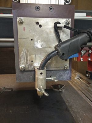
- A MIG welder and a modified weld gun to accept turning on and off signal
- A custom parts to hold a weld gun (See Figure 2)
- A wire to connect output from the control unit to the weld gun.
- A cylinder of shield gas, the type of gas depend on the type of metal (e.g., RC25 for steel)
- A welding curtain
- A ventilation fan
Operation & Procedure[edit | edit source]
- Turn on the control unit before open Mach3 program.
- Open Mach3 and click Reset button (See Figure 3).
- Click Load G-Code button and select G-Code file (The file has to be .txt).
- Set the original (0,0,0) point by moving the mounted weld gun to the wanted position, the nozzle should be 8 mm height from the substrate and in the middle of the substrate (Depends on the 3D model.), then click Zero X, Zero Y, and Zero Z buttons.
- Dry run with the welder and the shield gas off. Make sure the welding will be inside the substrate. Otherwise, adjust the position to be so.
- Stop the dry run, click Stop button, and reset the position of the weld gun by clicking GOTO ZERO button.
- Turn on the welder and the shield gas (For steel, set shield gas to 25 Cubic Feet per Hour, CFH).
- Close the welding curtain for protection. Turn on the ventilation fan.
- Click Cycle Start button to start printing.
- Usually, there is a pause between layer generated by MOSTMetalCura. The bigger the part is the longer the pause should be in order to let it cool down (70 degree Fahrenheit). The pause time can be set in MOSTMetalCura. User can manually stop the printing by click Stop button and click Cycle Start button to resume (Be careful! It will stop whatever it is doing and then skip to the next line of G-Code). Clean the nozzle if it is clogged up.
- Continue printing until finish all layers.
See also[edit | edit source]
- Open-source metal 3-D printer
- Low-cost Open-Source Voltage and Current Monitor for Gas Metal Arc Weld 3-D Printing
- MOST open-source metal 3-D printer v2
- Substrate Release Mechanisms for Gas Metal Arc Weld 3D Aluminum Metal Printing - how to get your print off the substrate with a hammer
- In Situ Formation of Substrate Release Mechanisms for Gas Metal Arc Weld Metal 3-D Printing
- Aluminum substrate cleaning for 3-D printing:MOST
- Hypoeutectic Aluminum–Silicon Alloy Development for GMAW-Based 3-D Printing Using Wedge Castings
- Open-source Lab
- Open source 3-D printing of OSAT
- Life-cycle economic analysis of distributed manufacturing with open-source 3-D printers
- Environmental impacts of distributed manufacturing from 3-D printing of polymer components and products
- Building research equipment with free, open-source hardware
- Delft University of Technology - MIG+ Prusa I3
- Weld 3D - 1st commercial spin off
- see literature on "wire arc additive manufacturing" (WAAM)
In the News[edit | edit source]
- Fine Print: 3D-Printed Replacement Car Parts Are Coming - Car and Driver, Fast Machines

