
Bike Pedal Example of Methodology for 3D-Printed Part Design


Determine Initial Feasibility
1) Is there an existing demand for the part or product? If yes, is there improved viability, feasibility, desirability or sustainability with 3-D printing?
Yes, there is an existing demand. Black mamba bikes ridden in East Africa are often ridden without pedals because the existing pedals fail. Replacements to existing pedals often needed, but not readily available.
Viable
Yes, a 3D printing service bureau could sell replacement pedals in East Africa.
Desirable
Yes, pedals are desired by those who do not have working pedals.
Feasible
Yes, it is technically feasible to print a bike pedal.
2) Is there an existing offering/part made by traditional manufacturing processes?
Yes.
If Yes, is there a benefit to 3-D printing the part? (e.g. geometry complexity, customization, density, rapid prototyping, reduce lead times, or unique 3D printing material)?
A pedal could be 3D printed in a remote location where there are not existing pedals for sale.
3) Is it feasible to 3D print part?
Is the the volume of part less than the build envelope?
Yes, a pedal is approximately 400 cubic centimeters and the build envelope for the MOST Delta has a 25cm diameter and a 24cm high cylinder.
Is the maximum operating temperature range for part less than the glass transition temperature for the printing filament?
Yes, the highest recorded temperature recorded in Kenya is 42.5 degrees C, while the glass transition temperature for PLA is between 50 and 60 degrees C.
4) Is there an existing CAD Model or STL file for part?
Yes, Black Mamba Bike pedal.
5) Determine and quantify necessary mechanical properties, standards, and loads for part.
The following testing methods and standards are given by SASO.[1]
Pedal-spindle impact test. Release 15kg from 200mm to strike pedal and spindle.
Pedal-spindle - dynamic durability test. 100,000 revolutions at 100 per min with 30kg mass attached to tension spring.
Static strength test. Apply vertical downward force of 700N to pedal for 1 min.
6) Prioritize necessary mechanical properties, standards, and loads for part.
Static strength test was selected due to simplicity. The vertical downward force was increased to 1000N for FEA simulation.
Model
[edit | edit source]7) Model existing part or prototype.
OpenSCAD was selected among the opensource software packages.
The existing File:Model of Pedal.scad was opened in OpenSCAD.
-
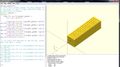 OpenSCAD Model

Export a STL file in OpenSCAD.
8) Convert STL file to IGES using FreeCAD.
	Open .stl file in FeeCAD.
	Save part as IGES (.igs)
9) Conduct Finite Element Analysis (FEA).
ANSYS was selected for FEA.
Import IGES (.igs) file into ANSYS.
Analysis: Structural
Element Type: Solid 183 or Solid 187
Load: 1000N
Young's Modulus: PLA - 3.5 GPa
Poisson's Ratio: 0.36
-
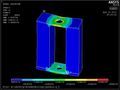 ANSYS Mesh of Pedal

10) Determine if part should be 3D printed based on (FEA).
Based on FEA the largest stress will concentrate around the spindle.
11) Select the most appropriate 3D printing filament.
PLA was selected as the best filament.
Prototype
[edit | edit source]12) Import CAD file into slicing software.

13) Determine optimal printing build parameters in slicing software with regard to necessary mechanical properties, standards, and loads.
Orientation: Vertical
Cura Settings Used:
From the Cura screen, select Machine>Machine settings. Set:
E-steps per 1mm filament to 0
Maximum width (mm) to 252 (the printer diameter)
Maximum depth (mm) to 252 (the printer diameter)
Maximum height (mm) to 250
In the Basic tab
Layer height (mm): 0.25
Shell thickness (mm) 1.4
Bottom/Top thickness (mm): 0.5
Fill density (%): 10
Print speed (mm/s): 70
Printing temperature (C): 210
Filament Diameter (mm): 1.75
Flow (%) 100
In the Advanced tab
Travel speed (mm/s): 250
14) Export G-Code from slicing software and import G-Code file into 3D printing software.
15) Select printing software.
Pronterface was selected.
Settings:
Printer Settings Tab
Baud Rate: 115200
X & Y manual feedrate: 4800
Z manual feedrate: 4800
Width:252
Depth:252
Height:250
Select the Check box that says circular build platform
16) Ensure printer is calibrated.
The Calibration Tutorial method was used.
17) Print part.
	RepRap printing protocol: MOST
	3D Printing Basics:MOST
	MOST Reprap Printing Lessons
-
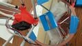 Printed Part
Test
[edit | edit source]18) Test printed part to failure. Kevin Johnson, kevinj@mtu.edu, is the person that is in charge of the lab in the MEEM.
	Testing apparatuses are found in rooms S003 and S008 of the MEEM at MTU.
	A variety of tests may be completed. (e.g. tension, compression, fatigue, impact, cyclical loading, etc.)
	The supervisor of the lab must be contacted to be trained with any of the machinery that is to be used.
	Appropriate load cells and attachments must be selected depending on the part and test being completed.
The static strength test was using SASO[1] methods for the pedal.
Apply vertical downward force of 700N to pedal for 1 min.
19) Does part fail as expected in FEA simulation?
Yes, part fails along spindle.
20) Does part meet necessary mechanical properties, standards, and loads for part?
No, part does not withstand 700N static strength test.
Economic/Social Feasibility
[edit | edit source]21) Cost Analysis
The equation below can be used to determine the cost of printing a part:
		 (Op) = (E)(Ce) + 1/1000(mf)(Cf) [2]

		 Op: Operating costs for the RepRap-produced products
		 E: 0.25 (kW-hr)
		 Ce: 0.12 (US$/kw-hr)
		 mf: 69 (g)
		 Cf: 19 (US$/kg)
$1.34 = (0.25)(0.12) + 1/1000(69)(19)
22) Quantify why 3D-Printed product is better than existing offerings.
	 A pedal in Kenya costs 280 Kenyan Shillings = $3
	 A 3D printed pedal costs $1.34.
Therefore, a 3D printed pedal is 45% of the cost of an existing pedal.
23) Qualify why 3D-Printed product is better than existing offerings.
A 3D printed pedal consumes less energy, uses less material, and is more environmentally friendly.
24) Continue iterative design process to optimize part for end user.
	Because the 3D printed part did not meet the load requirements for a 3D printed pedal, a new model was created.
	File:Version 2 Pedal.scad
-
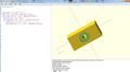 OpenSCAD Pedal 2

The second pedal was modeled as a solid object and printed with 100% infill to increase strength.

The iterative design methodology above should be repeated to optimize the part to meet all of the requisite design parameters.
See also
[edit | edit source]References
[edit | edit source]| Authors | |
|---|---|
| License | CC-BY-SA-3.0 |
| Cite as | Wjaitken (2015–2025). "Bike Pedal Example of Methodology for 3D-Printed Part Design". Appropedia. Retrieved July 10, 2026. |