MOST Planetary Gearbox and MOST Geared Extruder Drive
A planetary gearbox (more appropriately, https://en.wikipedia.org/wiki/Planetary_gearbox Epicyclic gearing) is a compact and efficient transmission. The MOST planetary gearbox is used in a number of applications in the MOST 3-D printer research program.
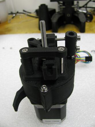
This assembly guide actually covers the complete assembly of the MOST Geared Extruder Drive, which is derived from http://airtripper.com/1071/airtrippers-bowden-extruder-v3-updated-design/ Airtripper's Bowden Extruder. Assembly of the gearbox is essentially unaffected by the geometries of the motor and output ends, in this case a vertical mount motor end and a MOST extruder block output.
Airtripper's Bowden Extruder is a great platform that has been improved upon:
The drive body has been placed atop a 4.62:1 planetary gearbox, eliminating torque issues.
The filament path has been straightened so there is little to no bending around the gear, reducing power requirements and making possible live swapping of filament.
Gaps between the drive gear and filament openings have been reduced helping to minimize jamming.
The OpenSCAD design has been parameterized allowing for easy manipulation of the design and permitting one line switching between 1.75mm and 3mm filament drives.
An infeed tube has been added to facilitate live swapping of filament. Even very short pieces of filament can be introduced with very few jams.
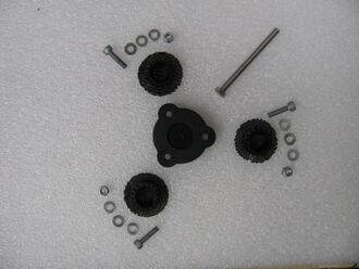
Planetary carrier parts (624zz bearings are missing from photo).Remove the raft material from the base of the three planetary gears with a sharp knife. Clean raft material and any protuberances from the face of the gear teeth with a sharp knife.
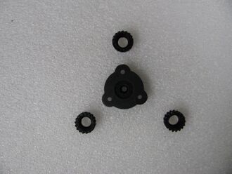
Planetary carrier printed parts after prep.Remove the support material in the planetary carrier's nut trap and ream the output shaft hole with an appropriately sized drill bit. Ream the M4 screw holes with a 4mm drill bit.
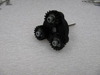
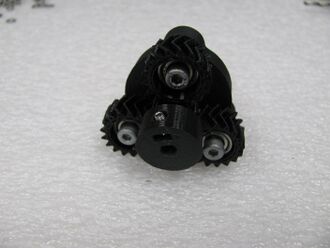
Planetary carrier pre-assembled.Press the output shaft (appropriately sized hex head cap screw) through the center of the planetary carrier so that the head of the screw is fully recessed into the nut trap.
Place a 624zz ball bearing in the recess provided in each of the three planetary gears.
Pass the M4 x 16mm screws through the bearing with the head of the screw on the same side as the bearing recess. Do not put a washer between the screws' heads and bearings.
Press the three M4 nylock nuts into the nut traps in the planetary carrier.
Place three M4 flat washers on the ends of the M4 screw in the planetary gears and thread loosely into the nylock nuts in the planetary carrier.
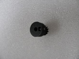
Assembled sun gear.Clean flashing from the base of the sun gear's set screw nut trap and motor shaft recess with a sharp knife. Ream the set screw hole with a 3mm drill bit. DO NOT ream the motor shaft recess as it matches the motor's D-profile shaft.
Press an M3 nut into the sun gear's set screw nut trap and start the M3 x 8mm cup point set screw into the nut with the cup end facing towards the motor shaft recess. Do not thread the set screw into the recess.
Test fitting sun gear UP SIDE DOWN.Test fit the sun gear on the motor shaft. The gear may slide onto the shaft easier with the teeth facing towards the motor. For assembly, the gear will be oriented with the teeth facing away from the motor. Remove the sun gear after assuring it fits snugly on the motor's shaft.
Planetary carrier and sun gear.Work the sun gear into the central space between all of the planetary gears ensuring that the teeth of the gears properly meshes. Do not force in the gear as teeth can be damaged.
Tighten the M4 screws, securing the planetary gears firmly to the planetary carrier. Ensure that the the sun gear freely engages and rotates the planetary gears.
Remove protuberances from the gear teeth in the annulus halves with a sharp knife.
Checking fit of annulus halves.Check the fit of the two annulus gear halves. The shorter, input half is placed on the sun gear side of the planetary assembly, the thicker, output half is placed on the output shaft side. The annulus gears have a fiduciary in the form of a pointed case screw boss - the pointed bosses should all align.
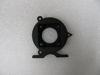
Prepared motor end.Remove the support material from the motor end with a sharp knife ensuring that the set screw access port is thoroughly cleared of obstructions. Ream the motor mount holes with a 3mm drill bit.
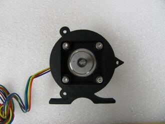
Motor attached to motor end.Attach the NEMA stepper motor to the motor mount with suitably sized screws.
Prepare the output end; clean with a sharp knife and ream out holes, especially the output shaft hole. Press in those nuts required for mounting components to the output end. For the geared extruder drive shown:
Extruder end - M3 nuts pressed into recesses on back.Ream the two holes for the idler pivot linking rod mounts with a 3mm drill bit.
Ream the filament path with the appropriately sized drill bit (2mm for 1.75mm filament, 3mm for 3mm filament).
Press in two M3 nuts in the locations where the M3 x 30mm screws secure the idler pivot linking rod.
Extruder end - drive gear and bearing in place.Back out the Mk7 drive gear's set screw such that the shaft hole is clear and press into it's recess. The recess has an appropriately sized, angled diameter portion to facilitate insertion - press the gear in at an angle and then flat against the base of the extruder block.
Set the MR105zz ball bearing on top of the drive gear.
Place the output bearing on the output shaft. The output bearing for the extruder drive shown is a 625zz bearing.
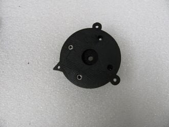
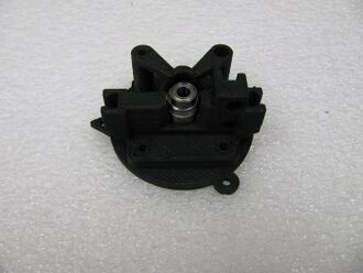
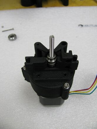
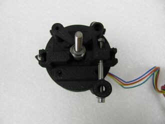
Pressed together gearbox.Slide the output shaft with bearing into the central hole in the output end and press the output bearing into its recess in the output end aligning the pointed case screw bosses. For the geared extruder drive shown, pass the output shaft through the Mk7 drive gear and MR105zz bearing.
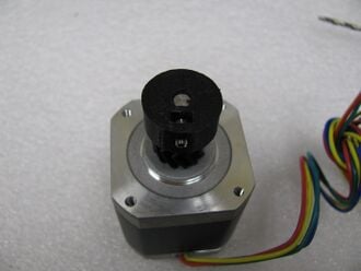
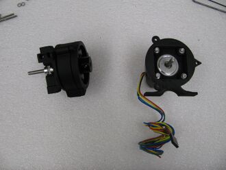
Aligning shaft and sun gear.Rotate the motor's shaft so that the flat portion is facing the set screw access port.
Align the sun gear such that the set screw is facing the set screw access port on the motor end and press the assembly onto the motor.
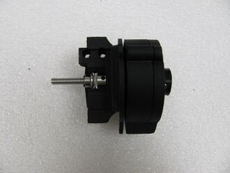
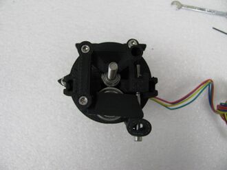
Assembled gearbox.Pass the M3 x 30mm socket head cap screws, with M3 nuts, through the case screw holes and secure with an M3 flat washer and M3 nut. DO NOT tighten too much at this stage - the gear box should be exercised by making several rotations before tightening the screws.
Tighten the sun gear's set screw, which should be visible through the set screw access port in the motor end.
Lubricate the gearbox with spray-on white lithium grease, placing the hose from the bottle into the set screw access port. Lubricant will leak from the gearbox an diffuse through the porous prints - be prepared to catch drips!
Exercise the gearbox by providing power to the motor and making several rotations - the longer the better. Rotation can be helped along by placing jammed nuts on the output shaft and using a wrench when the gearbox jams. Do not apply too much force, they are, afterall, just plastic gears.
After exercising the gearbox, tighten the case screws and check that the gearbox still rotates.
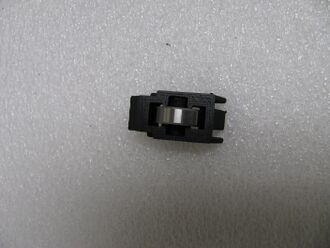
Assembled idler.Remove flashing from the idler housing with a sharp knife.
Snap or cut off the base on the idler shaft. Cut off all remaining protuberances from the shaft.
Slide the shaft through the 608zz bearing.
Press the shaft and bearing into the idler housing.
Pass a short length of the appropriate filament through the entire filament path. Move the Mk7 drive gear such that the filament engages it in the center of the hobbed portion of the drive gear. Tighten the drive gear's set screw when it is in the proper position.
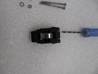
Getting ready to drill holes in hose.Using the idler housing as guide, drill a hole through the 1/4" fuel line with a 3mm drill bit.
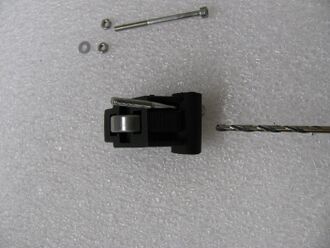
Setting up the second hole in the hose.Push one of the M3 x 40mm or 45mm screws with a washer through the drilled hole in the fuel line and place the screw in one of the slots in the idler housing. Using the housing as guide, drill the second 3mm hole in the fuel line.
Preloader on extruder block.Pass the remaining M3 x 40mm or 45mm screw through the newly drilled hole such that both screws' heads are on the same side of the fuel line, completing the preloader.
Idler pivot linking rod on extruder end.Attach the preloader to the extruder block by passing the ends of the preloader's screws through the matching holes in the extruder block. Start M3 nuts on the screws and pull the nuts back into the recess in the extruder block.
Idler on extruder end.Remove flashing from the idler pivot linking rod and ream the holes with a 3mm drill bit.
Pass the M3 x 30mm socket head cap screws through the holes in the linking rod with the screw heads sitting fully in the recesses provided.
Attach the idler pivot linking rod to the extruder block. Tighten the screws.
Attach the idler assembly to the pivot screw and engage the preloader.
Thread the appropriate sheath retainer (M4 nut for 1.75mm filament, M6 nut for 3mm filament) onto the end of the Bowden sheath and pres the nut into the slot on the preloader side of the extruder block.
Prepare a short infeed tube similar to the Bowden sheath, with only one threaded end, and slide the nut into the slot on the opposite side of the extruder block.