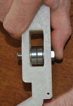
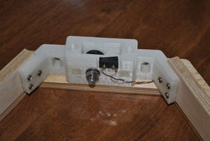
[[File:Athena idler end assembly.JPG|thumb|Completed idler end assembly, bottom.]]
{| style="margin:auto"
|-style="vertical-align:top;"
[[File:Athena idler end assembly top.JPG|thumb|Completed idler end assembly, top.]]
|[[File:athena_end_idler_material.JPG|thumb|400px|alt=Idler end materials|Idler end materials. Soldered limit switch, M2 screws and washers and 340mm round plywood not pictured.]]
{|class="wikitable" style="margin:auto"
{{Athena menu}}
|+Materials
!Description
''' Materials '''
!Count
|-
[[File:Athena end idler material.JPG|thumb|Idler end materials. Soldered limit switch, M2 screws and washers and 340mm round plywood not pictured.]]
[[File:Athena end idler tools.JPG|thumb|Necessary tools for Idler end. Note that a stubby screwdriver will be required if a right angle driver is unavailable.]]
|-
|M8 x 40mm bolt
* 2.5mm hex key
|3
* Precision knife
|-
* 13mm wrench
|M8 nut
* Small blade screwdriver
|3
* 3mm drill bit and holder
|-
* Screwdriver (right-angle driver preferred)
|M8 flat washer
* Epoxy stirring stick
|9
* Epoxy mixing pallet
|-
|608zz bearing
== Note ==
|6
|-
|colspan="2"|2-part plastic epoxy
|}
|
[[File:athena_end_idler_tools.JPG|thumb|400px|alt=Necessary tools|Necessary tools for Idler end. Note that a stubby screwdriver will be required if a right angle driver is unavailable.]]
{|class="wikitable" style="margin:auto"
|+Tools
|-
|2.5mm hex key
|-
|Precision knife
|-
|13mm wrench
|-
|Small blade screwdriver
|-
|3mm drill bit and holder
|-
|Screwdriver (right-angle driver preferred)
|-
|Epoxy stirring stick
|-
|Epoxy mixing pallet
|}
|}
=Note=
* '''DO NOT REAM''' the small holes in the rectangular pockets where the limit switches are mounted (see last steps in this page for clarification). The screws will themselves form threads in the plastic (plastiform threads) when you attach the switches to the idler ends.
* '''DO NOT REAM''' the small holes in the rectangular pockets where the limit switches are mounted (see last steps in this page for clarification). The screws will themselves form threads in the plastic (plastiform threads) when you attach the switches to the idler ends.
* The limit switches are held in place with both screws and epoxy. It's imperative that the limit switches do not move once attached to the idler ends. The printer will not home to the same position if switches are loose, causing endless problems with printer calibration.
* The limit switches are held in place with both screws and epoxy. It's imperative that the limit switches do not move once attached to the idler ends. The printer will not home to the same position if switches are loose, causing endless problems with printer calibration.
=Procedure=
== Procedure ==
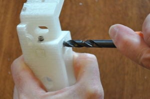
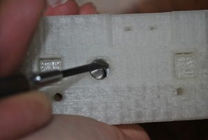
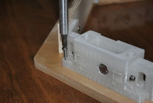
# [[File:athena_idler_assembly-bore.JPG|thumb|right|Opening the guide rod hole.]][[File:athena_prep_bar_clamp.JPG|thumb|right|Ream bar clamp.]]Clean the idler ends with a sharp knife, removing any protrusions from the faces in the interior of the idler box. Use M8 and M3 drill bits to ream all of the holes. Use an M3 drill bit to ream the hole of the bar clamps. Clear all protrusions from the linking board mount tabs.{{clear}}
# [[File:athena_idler_assembly-clamp-nut.JPG|thumb|right|Putting the nut in the bar clamp.]]Put an M3 nut in the nut trap in the bar clamp and push it in with a pair of pliers.{{clear}}
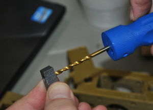
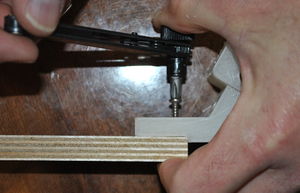
# [[File:Athena idler assembly-bore.JPG|thumb|Opening the guide rod hole.]][[File:Athena prep bar clamp.JPG|thumb|Bore through the bar clamp with a 3mm drill bit.]]Clean the idler ends with a sharp knife, removing any protrusions from the faces in the interior of the idler box. Use 8mm and 3mm drill bits to ream all of the holes. Use a M3 drill bit to bore the hole all the way through the bar clamps. Clear all protrusions from the linking board mount tabs. '''Do not bore the 8mm holes all the way through - just ream the hole with the drill bit!'''{{Clear}}
# [[File:athena_idler_assembly-clamp-insert.JPG|thumb|right|Inserting the bar clamp.]]Insert the bar clamps in the idler end.
# [[File:Athena idler assembly-clamp-nut.JPG|thumb|Putting the nut in the bar clamp.]]Put an M3 nut in the nut trap in the bar clamp and push it in with a pair of pliers.{{Clear}}
# [[File:athena_idler_assembly-clamp-fix.JPG|thumb|right|Fixing the bar clamp.]]Put an M3 washer on an M3 x 16 screw for every bar clamp and insert it in the idler end. Do not tighten the screw at all, because the guide rod first needs to be inserted.
# [[File:Athena idler assembly-clamp-insert.JPG|thumb|Inserting the bar clamp.]]Insert the bar clamps in the idler end.
# The idler is best assembled in steps, inserting a piece, advancing the bolt and then inserting the next piece. The order of items on the bolt, starting from the hex head will be idler end-washer-608zz-608zz-washer-idler end-washer-nut:{{clear}}
# [[File:Athena idler assembly-clamp-fix.JPG|thumb|Fixing the bar clamp.]]Put an M3 washer on an M3 x 16 screw for every bar clamp and insert it in the idler end. Do not tighten the screw at all, because the guide rod first needs to be inserted.
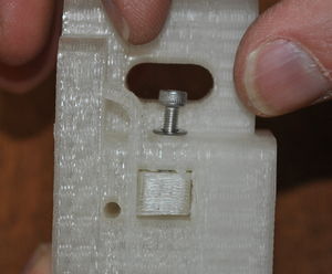
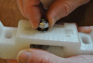
## [[File:athena_idler_assembly01.JPG|thumb|right|Start the bolt through an idler end.]]Start the M8 x 40mm bolt through the idler end from the side having the hexagonal relief for the bolt head.{{clear}}
# The idler is best assembled in steps, inserting a piece, advancing the bolt and then inserting the next piece. The order of items on the bolt, starting from the hex head will be idler end-washer-608zz-608zz-washer-idler end-washer-nut:{{Clear}}
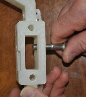
## [[File:athena_idler_assembly02.JPG|thumb|right|Put a washer on.]]Push the bolt in only until the bolt just extends into the idler box and then place an M8 washer over the end of the bolt.{{clear}}
## [[File:Athena idler assembly01.JPG|thumb|Start the bolt through an idler end.]]Start the M8 x 40mm bolt through the idler end from the side having the hexagonal relief for the bolt head.{{Clear}}
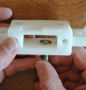
## [[File:athena_idler_assembly03a.JPG|thumb|right|Put on the first bearing.]]Advance the bolt a bit more and place one of the 608 bearings on it.{{clear}}
## [[File:Athena idler assembly02.JPG|thumb|Put a washer on.]]Push the bolt in only until the bolt just extends into the idler box and then place an M8 washer over the end of the bolt.{{Clear}}
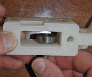
## [[File:athena_idler_assembly03.JPG|thumb|right|Put on the second bearing.]]Repeat with another 608 bearing.{{clear}}
## [[File:Athena idler assembly03a.JPG|thumb|Put on the first bearing.]]Advance the bolt a bit more and place one of the 608 bearings on it.{{Clear}}
## [[File:athena_idler_assembly04.JPG|thumb|right|A washer between the bearing and then a washer and nut to secure.]]Put an M8 washer on the end of the bolt.{{clear}}
## [[File:Athena idler assembly03.JPG|thumb|Put on the second bearing.]]Repeat with another 608 bearing.{{Clear}}
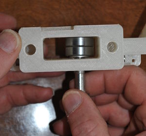
## [[File:athena_idler_assembly05.JPG|thumb|right|Aligning the second washer.]]Use a small screwdriver to align the washer so the bolt can go through the hole.{{clear}}
## [[File:Athena idler assembly04.JPG|thumb|A washer between the bearing and then a washer and nut to secure.]]Put an M8 washer on the end of the bolt.{{Clear}}
## [[File:athena_idler_assembly-bolt.JPG|thumb|right|The bolt in the relief.]]Push the bolt into the hexagonal relief.{{clear}}
## [[File:Athena idler assembly05.JPG|thumb|Aligning the second washer.]]Use a small screwdriver to align the washer so the bolt can go through the hole.{{Clear}}
## [[File:athena_idler_assembly-close.JPG|thumb|right|Adding a washer and nut.]]Place a washer and finally a nut on the opposite end.{{clear}}
## [[File:Athena idler assembly-bolt.JPG|thumb|The bolt in the relief.]]Push the bolt into the hexagonal relief.{{Clear}}
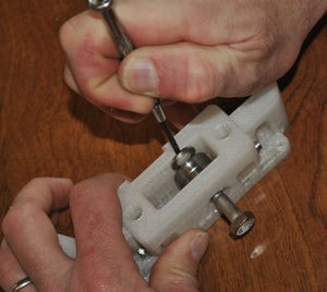
## [[File:athena_idler_assembly-tight.JPG|thumb|right|Tightening the idler.]]Tighten the nut, thereby pulling the bolt all the way into the relief.
## [[File:Athena idler assembly-close.JPG|thumb|Adding a washer and nut.]]Place a washer and finally a nut on the opposite end.{{Clear}}
## [[File:athena_idler_assembly-bolt_cap.JPG|thumb|right|Head of the bolt completely seated in idler end.]].{{clear}}
## [[File:Athena idler assembly-tight.JPG|thumb|Tightening the idler.]]Tighten the nut, thereby pulling the bolt all the way into the relief.
# Repeat with remaining two idler ends.{{clear}}
## [[File:Athena idler assembly-bolt cap.JPG|thumb|Head of the bolt completely seated in idler end.]].{{Clear}}
# If linking boards (210mm x 42mm x 12mm) do not have pilot holes drilled in them and you wish them to, follow directions [[Athena_pilot_holes|here]] before proceeding.
# Repeat with remaining two idler ends.{{Clear}}
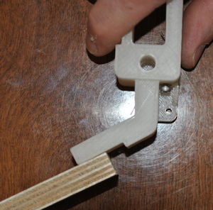
# [[File:athena_idler_assembly-link1.JPG|thumb|right|The linking board ready to be placed.]][[File:athena_idler_assembly-link2.JPG|thumb|right|The linking board in place.]]With the idler end laying on the table, flanges down, position a linking board so that the board butts firmly against the tab stop in the printed idler end. The board and idler end must be flat against the table.{{clear}}
# If linking boards (210mm x 42mm x 12mm) do not have pilot holes drilled in them and you wish them to, follow directions [[Athena pilot holes|here]] before proceeding. '''Make sure the short (210mm) linking boards are being assembled to the idler ends!'''
# [[File:athena_idler_assembly-screws.JPG|thumb|right|Screwing the linking board to the idler.]]Start three #6 x 3/4” sheet metal screws into the tab and linking board but do not tighten until the position of the board is checked – it must be firmly butted against the stop on the idler mount and both idler mount and board flat on the work surface. Once in position, tighten the screws.{{clear}}
# [[File:Athena idler assembly-link1.JPG|thumb|The linking board ready to be placed.]][[File:Athena idler assembly-link2.JPG|thumb|The linking board in place.]]With the idler end laying on the table, flanges down, position a linking board so that the board butts firmly against the tab stop in the printed idler end. The board and idler end must be flat against the table.{{Clear}}
# Repeat with another linking board on the other side of the idler end.{{clear}}
# [[File:Athena idler assembly-screws.JPG|thumb|Screwing the linking board to the idler.]]Start three #6 x 3/4" sheet metal screws into the tab and linking board but do not tighten until the position of the board is checked – it must be firmly butted against the stop on the idler mount and both idler mount and board flat on the work surface. Once in position, tighten the screws.{{Clear}}
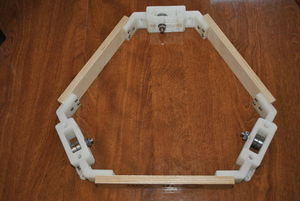
# [[File:athena_idler_assembly-triangle.JPG|thumb|right|The completed triangle.]]Continue with remaining linking board and other two idler ends. When complete, the idler ends should form the apexes of an equilateral triangle and the whole assembly should lie flat on the table top without rocking, flanges down.{{clear}}
# Repeat with another linking board on the other side of the idler end. '''Make sure the last linking board is attached to the correct side of the idler end so that one of the idler ends isn't upside-down in the final assembly!'''{{Clear}}
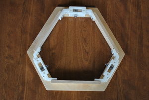
# [[File:athena_align_donut.JPG|thumb|right|Align the donut with the idler triangle.]][[File:athena_attach_donut.JPG|thumb|right|Attach the donut to the idler triangle.]]Select the side of the donut you wish to face outward and place that side down on the work surface. Place the triangle on the donut with the flanges facing it and line the two up. Note that the hexagon has two different length sides - the shorter sides mate with the idler ends, longer with linking boards. Secure the two together with six #6 x 3/4" screws.{{clear}}
# [[File:Athena idler assembly-triangle.JPG|thumb|The completed triangle.]]Continue with remaining linking board and other two idler ends. When complete, the idler ends should form the apexes of an equilateral triangle and the whole assembly should lie flat on the table top without rocking, flanges down.{{Clear}}
# [[File:Athena align donut.JPG|thumb|Align the donut with the idler triangle.]][[File:Athena attach donut.JPG|thumb|Attach the donut to the idler triangle.]]Select the side of the donut you wish to face outward and place that side down on the work surface. Place the triangle on the donut with the flanges facing it and line the two up. Note that the hexagon has two different length sides - the shorter sides mate with the idler ends, longer with linking boards. Secure the two together with six #6 x 3/4" screws.{{Clear}}
# Prepare six M2 x 12mm screws with washers on them for securing the limit switches.
# Prepare six M2 x 12mm screws with washers on them for securing the limit switches.
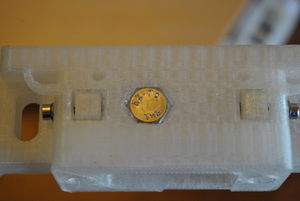
# [[File:athena_epoxy_switch_pockets.JPG|thumb|right|Apply epoxy on limit switch pocket.]]Mix a small amount of the two part plastic epoxy and apply to the switch pockets in the idler ends. Do not apply to the switch as to avoid epoxy getting into moving parts of the switch.{{clear}}
# [[File:Athena epoxy switch pockets.JPG|thumb|Apply epoxy on limit switch pocket.]]Mix a small amount of the two part plastic epoxy and apply to the switch pockets in the idler ends. Do not apply to the switch as to avoid epoxy getting into moving parts of the switch.{{Clear}}
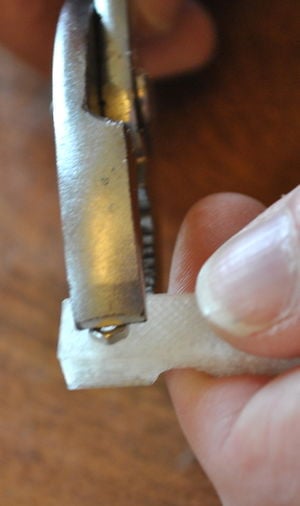
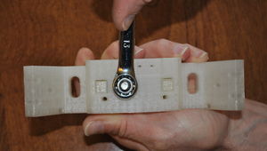
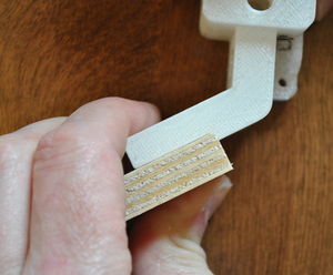
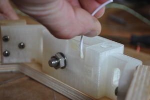
# [[File:athena_epoxy_limit_switch.JPG|thumb|right|Limit switch epoxied and screwed into pocket.]]Place one of the [http://www.appropedia.org/Soldering_and_Tinning:MOST assembled limit switches] into an epoxied switch pocket with the switch's '''switch tab opening towards the guide rod (see picture)'''. Working quickly, secure the switch with a pair of M2 screws. Repeat with remaining two switches.{{clear}}
# [[File:Athena epoxy limit switch.JPG|thumb|Limit switch epoxied and screwed into pocket.]]Place one of the [[Soldering and Tinning:MOST|assembled limit switches]] into an epoxied switch pocket with the switch's '''switch tab opening towards the guide rod (see picture)'''. Working quickly, secure the switch with a pair of M2 screws. Repeat with remaining two switches.{{Clear}}
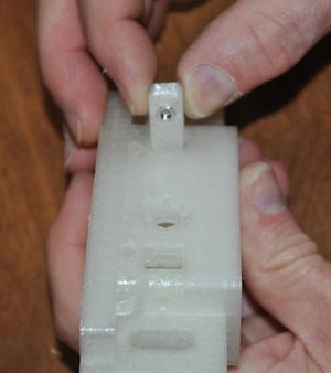
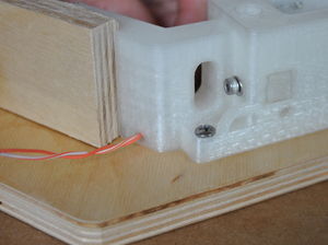
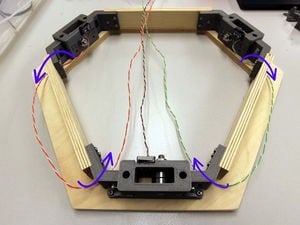
# [[File:athena_switch_wires.JPG|thumb|right|Pick one idler end and route wires neatly to it.]]Bring all of the limit switch wires to one idler end by passing wires through the holes in the idler ends. There are small holes close to where the donut and idler end meet - pass the wires from two of the switches through these holes and rout along the linking board/donut to the third idler end. Pass the wires through the similar small holes into the interior of the idler end.{{clear}}
# [[File:Athena switch wires.JPG|thumb|Pick one idler end and route wires neatly to it. '''Wires should take shortest path to the common idler end.''']] [[File:Athena switch wires2.JPG|thumb|Note that wires take shortest route to common idler end.]] Bring all of the limit switch wires to one idler end '''by the shortest route'''. There are small holes close to where the donut and idler end meet - pass the wires from two of the switches through these holes and rout along the linking board/donut to the third idler end. Pass the wires through the similar small holes into the interior of the idler end.{{Clear}}
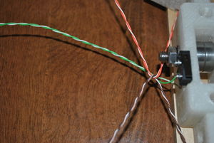
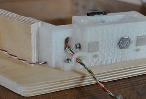
# [[File:athena_start_braided_wires.JPG|thumb|right|Make a single twist in the two pairs of wires from the other idler ends.]][[File:athena_braided_wires.JPG|thumb|right|Braid wires and pass through large hole on the right side (looking out) of the idler end.]]Twist the pairs of wires from the other two idlers once to start the braid and keep it centered. Braid the wires and pass the braid through the large hole on the right side of the idler end on the left side looking towards the interior of the idler end. Pass the braid through the loop on the exterior of the idler end.{{clear}}
# [[File:Athena start braided wires.JPG|thumb|Make a single twist in the two pairs of wires from the other idler ends.]]Twist the pairs of wires from the other two idlers once to start the braid and keep it centered.{{Clear}}
# [[File:Athena braided wires.JPG|thumb|Braid wires and pass through large hole on the left side of the idler end.]]Braid the wires. Rotate the idler assembly so the idler end with all the wires is facing you. Pass the braid through the large hole on the left side of the idler end and then through the loop on the exterior of the idler end.{{Clear}}
[[File:athena_idler_end_assembly.JPG|thumb|400px|center|Completed idler end assembly, bottom.]][[File:athena_idler_end_assembly_top.JPG|thumb|400px|center|Completed idler end assembly, top.]]
=Navigation=
{{template:Athena_Basic_Nav}}
[[category:3D printing]]
{{Page data}}
Latest revision as of 10:00, 16 September 2024
Completed idler end assembly, bottom.Completed idler end assembly, top.
DO NOT REAM the small holes in the rectangular pockets where the limit switches are mounted (see last steps in this page for clarification). The screws will themselves form threads in the plastic (plastiform threads) when you attach the switches to the idler ends.
The limit switches are held in place with both screws and epoxy. It's imperative that the limit switches do not move once attached to the idler ends. The printer will not home to the same position if switches are loose, causing endless problems with printer calibration.
Opening the guide rod hole.Bore through the bar clamp with a 3mm drill bit.Clean the idler ends with a sharp knife, removing any protrusions from the faces in the interior of the idler box. Use 8mm and 3mm drill bits to ream all of the holes. Use a M3 drill bit to bore the hole all the way through the bar clamps. Clear all protrusions from the linking board mount tabs. Do not bore the 8mm holes all the way through - just ream the hole with the drill bit!
Putting the nut in the bar clamp.Put an M3 nut in the nut trap in the bar clamp and push it in with a pair of pliers.
Inserting the bar clamp.Insert the bar clamps in the idler end.
Fixing the bar clamp.Put an M3 washer on an M3 x 16 screw for every bar clamp and insert it in the idler end. Do not tighten the screw at all, because the guide rod first needs to be inserted.
The idler is best assembled in steps, inserting a piece, advancing the bolt and then inserting the next piece. The order of items on the bolt, starting from the hex head will be idler end-washer-608zz-608zz-washer-idler end-washer-nut:
Start the bolt through an idler end.Start the M8 x 40mm bolt through the idler end from the side having the hexagonal relief for the bolt head.
Put a washer on.Push the bolt in only until the bolt just extends into the idler box and then place an M8 washer over the end of the bolt.
Put on the first bearing.Advance the bolt a bit more and place one of the 608 bearings on it.
Put on the second bearing.Repeat with another 608 bearing.
A washer between the bearing and then a washer and nut to secure.Put an M8 washer on the end of the bolt.
Aligning the second washer.Use a small screwdriver to align the washer so the bolt can go through the hole.
The bolt in the relief.Push the bolt into the hexagonal relief.
Adding a washer and nut.Place a washer and finally a nut on the opposite end.
Tightening the idler.Tighten the nut, thereby pulling the bolt all the way into the relief.
Head of the bolt completely seated in idler end..
Repeat with remaining two idler ends.
If linking boards (210mm x 42mm x 12mm) do not have pilot holes drilled in them and you wish them to, follow directions here before proceeding. Make sure the short (210mm) linking boards are being assembled to the idler ends!
The linking board ready to be placed.The linking board in place.With the idler end laying on the table, flanges down, position a linking board so that the board butts firmly against the tab stop in the printed idler end. The board and idler end must be flat against the table.
Screwing the linking board to the idler.Start three #6 x 3/4" sheet metal screws into the tab and linking board but do not tighten until the position of the board is checked – it must be firmly butted against the stop on the idler mount and both idler mount and board flat on the work surface. Once in position, tighten the screws.
Repeat with another linking board on the other side of the idler end. Make sure the last linking board is attached to the correct side of the idler end so that one of the idler ends isn't upside-down in the final assembly!
The completed triangle.Continue with remaining linking board and other two idler ends. When complete, the idler ends should form the apexes of an equilateral triangle and the whole assembly should lie flat on the table top without rocking, flanges down.
Align the donut with the idler triangle.Attach the donut to the idler triangle.Select the side of the donut you wish to face outward and place that side down on the work surface. Place the triangle on the donut with the flanges facing it and line the two up. Note that the hexagon has two different length sides - the shorter sides mate with the idler ends, longer with linking boards. Secure the two together with six #6 x 3/4" screws.
Prepare six M2 x 12mm screws with washers on them for securing the limit switches.
Apply epoxy on limit switch pocket.Mix a small amount of the two part plastic epoxy and apply to the switch pockets in the idler ends. Do not apply to the switch as to avoid epoxy getting into moving parts of the switch.
Limit switch epoxied and screwed into pocket.Place one of the assembled limit switches into an epoxied switch pocket with the switch's switch tab opening towards the guide rod (see picture). Working quickly, secure the switch with a pair of M2 screws. Repeat with remaining two switches.
Pick one idler end and route wires neatly to it. Wires should take shortest path to the common idler end.Note that wires take shortest route to common idler end. Bring all of the limit switch wires to one idler end by the shortest route. There are small holes close to where the donut and idler end meet - pass the wires from two of the switches through these holes and rout along the linking board/donut to the third idler end. Pass the wires through the similar small holes into the interior of the idler end.
Make a single twist in the two pairs of wires from the other idler ends.Twist the pairs of wires from the other two idlers once to start the braid and keep it centered.
Braid wires and pass through large hole on the left side of the idler end.Braid the wires. Rotate the idler assembly so the idler end with all the wires is facing you. Pass the braid through the large hole on the left side of the idler end and then through the loop on the exterior of the idler end.