Polarity refers to DC power - one of the conductors is positive (+) one is negative (- 'ground' on the controller board). Steps where polarity is a consideration are noted - pay close attention and make sure that the positive and negative conductors are in the correct locations before applying power to the printer! Consequences of failing to observe polarity are expensive.
There are three motors that control the movement of the printer. The motors are identified as U, V and W. When looking at the front, the extruder drive (with the fourth motor) is at the back of the printer. The U motor is on the left front, the V motor is on the right front and the W motor is in the back center on the apex with the extruder drive.
The Melzi controller expects a Cartesian robot, where every motor is directly controlling the movement in one of the Cartesian coordinate directions, X, Y, or Z. For this reason, the terminals are labeled with those coordinates. For a delta printer, the U motor connects to the X-terminals, V to the Y-terminals and W to the Z-terminals.
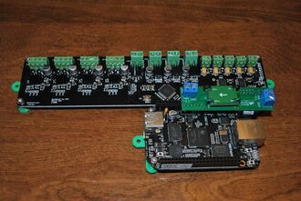
The bridge board is optional, but recommended. It provides more reliable communication between the Beaglebone Black and Melzi. The Melzi's USB connection has frequently proven unreliable. If the bridge board is not used, connect the two with a USB cable.
Loosen all of the screw terminals on the Melzi controller and insert a screwdriver into each terminal to insure that it is fully open. This will greatly ease insertion of wires in a later step.
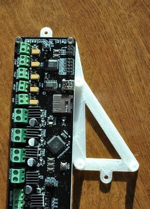
Mount the Melzi controller board to the electronics mount.Mount the Melzi controller to the large electronics mount with the USB socket facing towards the wider part of the printed mount with two M3 x 6mm screws(see photo). Do not tighten the screws yet - leave the board loose on the mount.
Mount the small electronics mount to opposite end of Melzi board.Mount the small electronics mount to the opposite end of the Melzi controller board with a pair of M3 x 6mm screws. Tighten the screws.
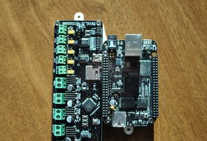
Mount the Beaglebone Black to the controller mount.Mount the Beaglebone Black to the large controller mount with three M3 x 6mm screws. Tighten the screws.
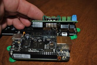
Note how pins line up between bridge board, Melzi and Beaglebone Black.Properly placed bridge board.Align the bridge board with the Melzi and Beaglebone Black so that the double row of female headers engage the male pin headers on the Melzi and the single row female pin header aligns with the matching male pin header on the Beaglebone Black. The remaining double row of male pin headers should then align with the end of the long double row female pin header on the Beaglebone Black. Once all of the pins are aligned, carefully and fully engage all the headers. Tighten the loose screws on the Melzi.
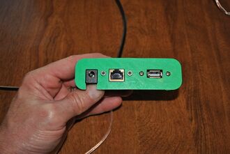
Attach connectors to panel.Snap off the support material on the connector plate (under the tabs) with a screwdriver and pliers. Remove flashing from openings with a knife and ream the holes with a 3mm drill bit. Secure the network and USB extension cables to the connector plate with supplied screws or M3 x 6mm screws. Slide the barrel connector into the slot built in the connector plate.
Press the connector plate into the slot in the linking board.Place the printer on a chair inverted so that the motor end faces up. Press the assembled connector plate into the slot cut in the motor-end linking board with the wires entering the base of the printer. Tabs on the connector plate should engage with the board, keeping it in place. If the connector plate is too loose in the slot and pulls out when a cable is disconnected, secure it with construction adhesive. Hold in place with tape while the adhesive sets.
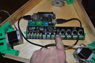
Connect network and USB extensions to Beaglebone Black. Engage the extension cables in their respective sockets on the Beaglebone black. Position the electronics in the base so that you can disengage network and USB connectors and all of the motor, limit switch and thermistor screw terminals can be accessed (see photo).
Secure the electronics to the base.When happy with the position, secure the electronics to the interior of the base with three #6 x 1/2" sheet metal screws.
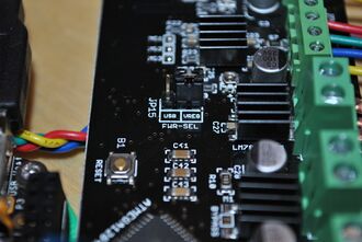
Mark the POSITIVE terminal on the Melzi.Locate the supply power terminals in the center Melzi board (marked POWER). Clearly mark the POSITIVE terminal (the terminal nearest the E-MOTOR terminal) with a permanent marker.
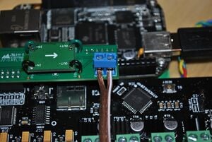
The Melzi power source jumper is in the middle of the board.Set the shorting block so the VREG pins are shorted as shown in the picture.
Set the printer on a chair so that the motor end faces upwards. When looking down at the motors, W, U, and V are in clockwise rotation with W being the motor on the apex having the extruder drive and spool holder mounted to it.
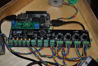
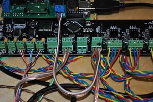
Wires can be tucked behind the controller board and secured to the standoffs with wire ties to keep things neat. Secured and well bundled wires are less likely to get entangled and pulled out of terminals.
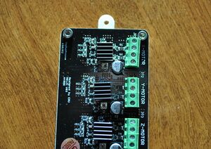
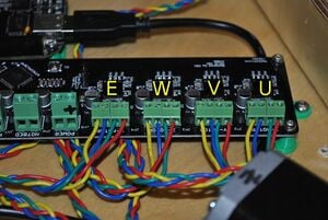
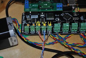
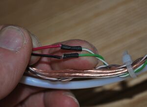
Follow the wiring carefully - click on picture to zoom in.Wire the motors as shown in the image, wiring the drive motors for U, V and W to X-MOTOR, Y-MOTOR and Z-MOTOR, respectively (see photo - note that connecting two motors to the wrong terminals will result in mirrored prints). The extruder motor is likewise connected to the controller to the terminal marked E-MOTOR. If motor leads are colored differently than shown, identify connected pairs of motor wires by touching the conductors together and noting if additional force is required to rotate the motor shaft. Wire pairs that increase resistance to rotation should occupy adjacent terminals (e.g. the pairs shown in the picture are red-green and blue-yellow).
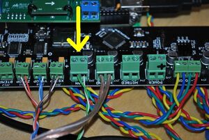
Connect limit switches.Connect the limit switch conductors to their respective axes e.g. the limit switch above the U motor is attached to the U limit switch (marked XSTOP), etc. There is no polarity concern.
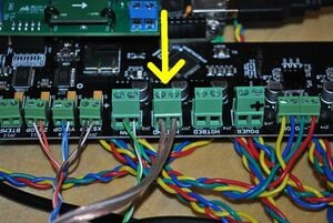
Wire hot end thermistor.Connect the hot end thermistor to its respective connectors on the controller board (marked ETEMP). There is no polarity concern.
Wire hot end resistor.Connect the hot end power resistor to its respective connector (marked HOTEND) on the controller board. There is no polarity concern.
Note the color of the 24ga wire soldered to the red (POSITIVE) wire of the fan - brown-white in this picture.Note the color of the 24ga wire soldered to the red (POSITIVE) wire of the end effector cooling fan.
Attach fan - Polarity matters.Polarity matters! Connect the fan to its terminal on the controller board (marked FAN); red (POSITIVE) wire of the fan to the positive terminal. If the fan does not turn on when the extruder exceeds 50°C, you likely have the wires reversed. The fan can be damaged if this is left to continue for too long.
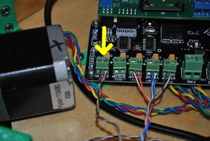
Attach power cable to bridge board - POLARITY MATTERS!.Polarity matters! Reversing polarity at this step will likely result in destruction of the Beaglebone Black upon application of power. Attach the 15cm (6") long speaker cable to the bridge board screw terminal nearest the screw terminals on the Melzi (see photo) taking note of the markings on the conductors and which terminal (positive or negative) each conductor is attached to. Tighten the screws.
Attach power from barrel connector socket to Melzi and bridge board. Melzi and bridge board are connected in parallel.Polarity matters! Reversing polarity at this step will likely cause destruction of both the Melzi and the Beaglebone Black upon application of power, producing about $100 worth of smelly, blue smoke. Connect both of the POSITIVE conductors from the barrel connector socket and the bridge board to the POSITIVE terminal on the Melzi. Connect both NEGATIVE conductors from the barrel connector socket and the bridge board to the NEGATIVE terminal on the Melzi. The Melzi and bridge board are connected to the barrel connector socket in parallel. Flattening the wires with pliers followed by trimming their widths greatly facilitates this step.
Attach glass build platform with hold downs and screws.Place Athena on the table, motor side down. Center the glass build platform on the bottom base and secure in place with three glass hold downs and #6 x 1/2" sheet metal screws.