
Briceland PV

| Type | Photovoltaic system |
|---|---|
| Authors | Kiva Mahoney |
| Location | Briceland, California |
| Status | Deployed |
| Years | 2006 |
| Uses | supply household items that need electricity |
This project was to install a photovoltaic (PV) array with sufficient capacity to support all of the household demands, including a electric refrigerator, as well as a wood shop. There is a micro-hydro system on the property as well that delivers power in the winter when the creek is running strongly but can not keep up with demand in the summer when the rains have stopped. For this reason we had to install a power source for the summer months. Briceland gets a lot of sun in the summer, so with the installation of this PV array there is now plenty of power all year-round.
Getting Started
[edit | edit source]Array Components
[edit | edit source]- Panels
- Breaker Box
- Outback MPPT charge controller
- Batteries
- Inverter
Array stand
[edit | edit source]- Post
- Array rack
Array Design
[edit | edit source]The PV array is made up of 8-120 watt modules so at peak power we should get 960 watts. Each panel is 12 volts and 6.82 amps. The panels are set up so that four of them are in series and the two sets of four panels are in parallel. In this way it is a 48 volt, 13.64 amp system. The panels are made by Evergreen Solar which is one of the only solar panel companies that is not owned by a big oil corporation. The String Ribbon technique Evergreen uses to fabricate their panels consumes half as much silicon as conventional processes.
Construction
[edit | edit source]The first step was to get the post in the ground and the rack set up. Following is a detailed list of how this was done.
- First we had to dig a hole deep enough to support the stand. Due to the size of the array, this hole had to be five feet deep. We dug the hole with Daniel's tractor, which is run off bio-diesel. (See Fig 1 and 2)
- In the bottom of the hole we laid 6 inches of gravel. This gravel is to allow for the drainage of any water that might find its way into the post.
- Once the gravel was down we put in the concrete form. This consisted of a ½ inch thick cardboard tube that is 16 inches in diameter. (see Fig 4)
- After the form was in we centered the stand with in it. The stand is a steel ½ inch, 16 inch diameter post. The post was to heavy for us to lift and move around once it was in the hole so we tied it to the tractor to lifted it up while I centered it and then lowered it back down. (see Fig 5 and 6)
- When the stand was in place it was time to pour the concrete. We used a mixer which was run off the electricity from a micro-hydro system we installed in the fall. This made the job go a lot quicker then if we had to mix all the bags by hand. In total we used 10 bags of quick-crete. When done it is important to make sure that the concrete is not level but raised up some. This is because it will shrink and settle down as it dries. (see Fig 7 and 8)
-
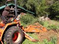 Fig 1: Digging hole.
 -
 Fig 2:
 -
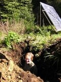 Fig 3: Checking the hole depth.
 -
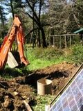 Fig 4: Concrete form.
 -
 Fig 5: Setting the stand.
 -
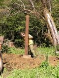 Fig 6: The stand.
 -
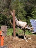 Fig 7: Pouring concrete.
 -
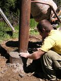 Fig 8: Finishing the concrete.


While the concrete was setting up we built the rack which came ready to assemble and was very easy to put together. It consists of a central bracket that sits on top of the post that acts as a pivot point, and lateral bars that the panels connect to. Once it was assembled on the ground we lifted it up and set it on top of the post.


Panel Setup
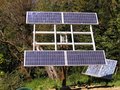
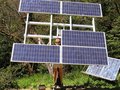
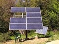
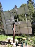
[edit | edit source]Once the rack was together it was time to install the panels. Both of these were designed to fit together very easily. Each panel attached to the rack in four places with a bracket that slid into one of the cross beams and then was bolted to the panel. These sliders allow the panels to be moved around once they are on the rack. As we put them on we tried to keep the weight balanced so we could still flip the rack to reach both sides.
-
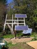 Two panels on.
 -
 Four panels on.
 -
 Five panels on.
 -
 One panel left.
 -
 One left.
 -
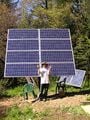 All panles up.


Wiring
[edit | edit source]Panel Wiring
[edit | edit source]Four of the panels we wired in series with each other and then the two sets of four panels we wired in parallel. These were ran through a fuse box before going on to the charge controller.


Charge Controller, Batteries, and Inverter
[edit | edit source]After the charge controller there is another fuse box before the batteries. Right now there are only two L-16 batteries in place which are too few for the power input from the array. Eventually we will have the charge controller hooked up to eight L-16 batteries. From the batteries the power goes two places. The first is to the DC circuits in the house and the second is to the inverter, each of these having individual fuses.
-
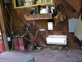 The old batteries and inverter.
 -
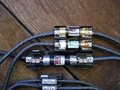 Fuses to charge controller.
 -
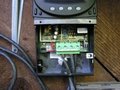 Charge controller wiring.
 -
 Charge controller reading.
 -
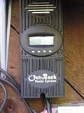 Charge controller.


Power
[edit | edit source]This we will know when we are able to hook the whole system up.
The End
[edit | edit source]
| Authors | |
|---|---|
| License | CC-BY-SA-3.0 |
| Cite as | Soysinlimites (2006–2026). "Briceland PV". Appropedia. Retrieved July 20, 2026. |