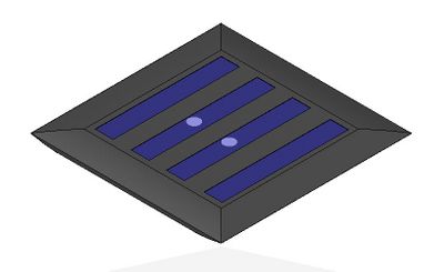
Partially prototyped -- needs full test with photovoltaics.. The main goal of this Mech425 project is to design a simple, cost effective indoor light source that can be used in areas of the world that do not have access to electricity or safe lighting at night. If this design proves viable, the technical specifications as well as methodology and costs will be available to anyone who has access to the internet or to programs such as the One Laptop Per Child (OLPC) Program.
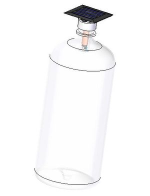
The proposed design utilizes a recycled bottle and cap (with a cap diameter equal to or greater than that of a 2L pop bottle) as a portable, durable platform for a high efficiency LED lighting system that is charged using a small solar panel. The bottle cap will house the lighting equipment and act as the bulb ballast and the pop bottle will act as the diffuser and stand.
Background[edit | edit source]
LED Technology[edit | edit source]
LED is an acronym for a lighting system known as a light-emitting diode. LED's are semiconductors that emit light when a junction is exposed to a forward biased electrical charge (electro luminescence). This application will use white LED's, which can be used as a much more efficient replacement for incandescent light bulbs. The main advantages of LED use are the efficiency and lifespan compared to standard incandescent bulbs. First of all, LED's produce many more lumens/watt of light than incandescent bulbs, resulting in a reduced power requirement as well as increased running time when powered by batteries. They also have extremely long lifetimes (anywhere from 10 000 to 100 000 hours) compared to incandescent bulbs (1000-2000 hours).[1][2][3]
These qualities have made LED lighting ideal for grass roots, low power applications such as this project, and have been used in similar endeavors. Some examples include:
- Barefoot Power, which develops AC and solar lighting products for the developing world and is involved with projects such as Lighting Africa and
- The Lumina Project[4]
- SOLLIGHT TM, which is a solar LED system designed for wide mouthed water bottles[5]
- Cosmos Ignite Innovations, which provides lighting solutions for developing nations.[6]
Lighting Issues Around the World[edit | edit source]
Approximately two billion people, almost 30% of the world population have no access to electricity, thus relying on fuel-based lighting, such as kerosene wick lamps and candles. This is a very dangerous alternative that is unsafe, expensive, and provides very inefficient lighting. Being limited by the amount of sunlight during the day makes it very difficult to perform tasks efficiently at night. The main problem is that these tasks include homework or studies by adults and children, and without proper lighting, reading books or chalkboards is impossible. This presents a barrier to education and economic development, not to mention literacy improvement. Efficient, self sufficient lighting can therefore impact the well being of people who cannot function efficiently after the sun has set.[7]
A major push to switch to LED lighting is the widespread use of dangerous, expensive fuels such as kerosene. Kerosene is very expensive for people living in poverty. In places such as rural India, purchasing enough kerosene to light a small household can represent more than 4% of a household budget. The light that these kerosene lamps produce is also very inefficient; LED's can produce more than 200 times the useful light. For example, an entire village can be lit using less energy than a single 100W normal bulb.[8]
Making the switch to solar powered LED lighting systems not only presents a more cost effective, efficient alternative, but also a much safer one. According to the World Health Organization, indoor air pollution from kerosene and other burned fuels used for indoor lighting and cooking is the cause of more than 1.5 million deaths to date .[8] There is also additional risk of fire when using kerosene, providing yet another reason to switch to LED lighting.
LED Light Source Design Requirements[edit | edit source]
The design must fulfill the following functional requirements in order to be an appropriate solution to the lighting problem:
- System Cost: The cost of the system must be minimized as much as possible in order for people in developing countries who survive on as little as $1 per day to afford it without marginalizing food and shelter requirements. If the cost is too high, people will not be able to cover the overhead, and will not be able to benefit from safe, efficient lighting.
- Simplicity: The design must be as simple as possible in order to minimize overhead costs and complexity. This simplicity will lead to increased durability and lifespan.
- Maintenance: The design must be easy to maintain, with little to know technical knowledge required. It must therefore be a contained unit that requires no additional maintenance other than initial installation.
- Self Sufficient: The light must be able to recharge and run itself without any additional charging or battery replacement. The solar cell must fully charge the battery when exposed to peak sunlight during the day, and the battery must retain the charge without replacement over a long period of time.
- Environmental Impact: The production and operation of the light must be optimized with regards to environmental impact. This means that the component choice must maximize the use of recycled materials and the end of life disposal must produce minimal impact.
- Ease of Use: The installation and use of the light must be as simple as possible in order to minimize the chance of confusion or degradation due to misuse.
The functional requirements have been weighted according to relative importance with respect to applications in developing nations. The results are shown in Table 1.
| Function Requirement | Importance Weighting |
|---|---|
| System Cost | 50 |
| Simplicity | 10 |
| Maintenance | 10 |
| Self Sufficient | 10 |
| Environmental Impact | 10 |
| Ease of Use | 10 |
| Total Weight | 100 |
Each of the functional requirements and their relative importance will be considered in the design of the LED lighting system. The first step is to design the circuit that will power the LED.
Circuit Design[edit | edit source]
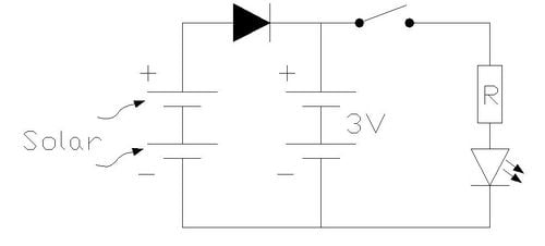
The first step in this light source design is the circuitry. A solar charged battery light circuit is relatively simple, because the energy input can be modeled as an external power source, and the battery can be charged constantly without backward current flow using a diode. The only problem with compact LED lighting systems is the limitation of voltage from small battery packages. AAA's and AA's (which will be used in this application) are limited to maximum 1.5V, which is half of the optimum voltage for a white LED. This problem leads to two distinct circuit design solutions; one that is simple and runs the LED at 3V but requires 2 batteries and one that is complex that runs the LED at the full voltage through the use of a voltage booster. The circuit diagram for the simple solution can be seen in Figure 1.
Figure 1: 2 Battery 'Simple' Circuit
| Ortho View |
|---|
|
This simple solution would result in suitable performance but would require 2 batteries (which is relatively expensive and environmentally costly)and depending on the LED choice, would not need a resistor. This layout can possibly extend the life of the light because it is running at a slightly lower voltage.
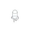
The components required the 'simple' circuit with 2 batteries totaling approximately 3V will be:
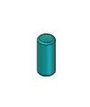
Battery:
Solar Panel:
Resistor:
Not required due to the limited voltage being supplied.
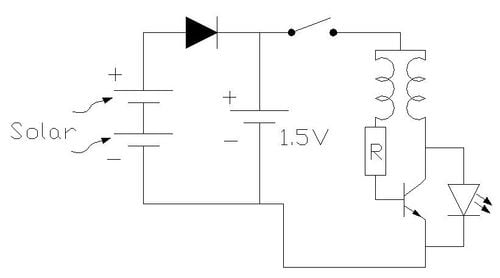
The diagram for the single 1.5V battery with a more 'complex' wiring solution can be seen in Figure 2.
Figure 2: Solar Charged 1.5V Boosted LED Lighting Wiring Schematic ('Complex' Layout)
| Ortho View |
|---|
|
This 'complex' solution would result in optimum lighting quality from the LED, but would significantly increase the cost of parts and manufacturing as well as limit the life of the device (voltage boosters are limited to a few hundred hours of runtime, depending on the voltage increase required[9]). The inductance based voltage booster can be made from a ring of ferrous material wrapped in 2 separate copper wires, and provides a simple, relatively cheap solution to the lack of voltage produced by the battery.[10] The main advantage is the reduction in reliance on 2 batteries, hence reducing the cost and environmental impact.[11]
The components required the 'complex' circuit with for a single 1.5V source boosted to approximately 4.5V will be:
Battery:
Solar Panel:
Resistor:
Circuit Economic Analysis[edit | edit source]
In order to determine which of the two wiring options is more suitable for this low cost, simple application, an economic evaluation must be performed. Whichever option provides more cost-effective parts and labor outcome will be used in the final design. Tables 2 and 3 show the summary of parts and costs in order to determine the total individual circuit costs. Please note that the labor costs have been approximated based on the possibility of manufacturing in China where the labor rate is lower .[12]
| Component | Price | Information | Vendor |
|---|---|---|---|
| AAA Battery[13] | $0.53 | BTY NIMH 1000 mAH AAA | Hotock Group |
| align="center" |$0.53 | BTY NIMH 1000 mAH AAA | Hotock Group | |
| Diode[14] | $0.28 | Schottkey 60V 15 mA Diode | STMicroelectronics |
| Switch[15] | $0.45 | DPDT Slide Switch | Anticsonline |
| LED[16] | $0.68 | 5mm White LED | PCToys |
| Solar Panel (4V)[17] | $5.48 | 4V 60 mA 0.24W | Keawin |
| Labor[12] | $1.20 | ||
| TOTAL | $9.12 |
| Component | Price | Information | Vendor |
|---|---|---|---|
| align="center" |$0.53 | BTY NIMH 1000 mAH AAA | Hotock Group | |
| align="center" |$0.28 | Schottkey 60V 15 mA Diode | STMicroelectronics | |
| align="center" |$0.45 | DPDT Slide Switch | Anticsonline | |
| Transformer | $0.45 | Ferrous ring with coil | N/A |
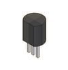
| Resistor[18] | $0.20 | 271-1321 10K resistor | Radioshack |
| Transistor[19] | $0.11 | BC549 30V 100mA limit | Fairchild Semiconductors |
| align="center" |$0.68 | 5mm White LED | PCToys | |
| Solar Panel (2V)[20] | $3.90 | 2V 70 mA 0.14W | Keawin |
| align="center" |$2.10 | |||
| TOTAL | $8.67 |
The excel file can be seen here: File:Wiring Cost Comparison.xls
The more complex, voltage boosting circuit is the least expensive to produce because of the lower power requirement for the solar cell as well as the reduction in number of batteries required. The only limiting factor may now be the lifespan of the voltage boosting transformer, which can be maximized by using high quality components as well as standardized construction procedures. The overall cost of $8.67 CAD is slightly higher than originally predicted for the wiring component of the design, but it can be minimized if it is mass produced. Also, if the product efficiency and environmental impact can be optimized, then the additional price is worthwhile.
Bottle Cap LED Fixture Design[edit | edit source]
There are two main methodologies that have been explored in order to develop a suitable appropriate technology designation for this design. The first of which relies on mass production (or at least semi-mass production) to justify the housing design as well as the parts purchases. The methodology relies on recycling all parts, which would be relatively difficult where there is little technology available, and designing based on parts available. The first methodology has been applied to develop a single part and assembly methodology that can be mass produced using injection molding and labor in China. The second methodology has been applied through the development of a prototype that utilizes the most recycled components as possible.
Custom Designed Fixture[edit | edit source]
Required Parts[edit | edit source]
The mass production design requires a larger investment on the part of a sponsor or company in the short term, but will provide people with a reliable, water resistant, efficient lighting source that requires minimal maintenance. This design involves the production of a central component housing with the purchase of multiple electrical components. The parts required for the design are as follows:
Housing[edit | edit source]
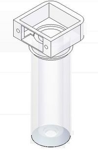
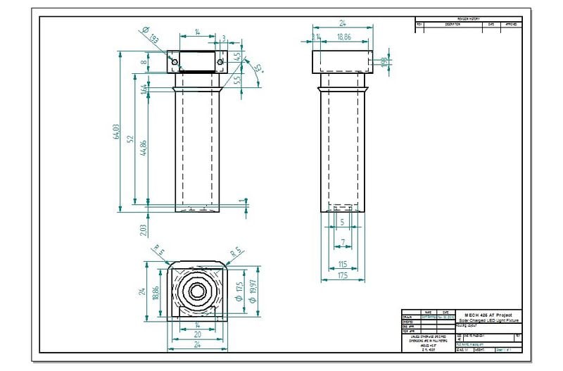
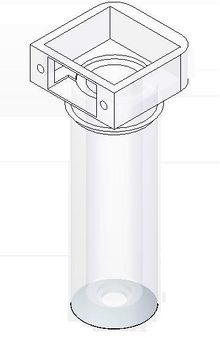
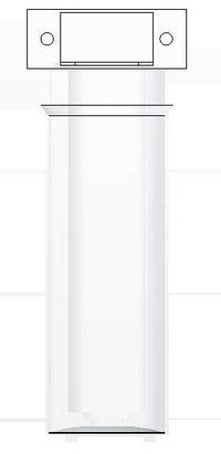
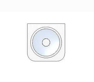
The part that must be manufactured is the housing for all of the components, and it can be seen in Figure 3, with it's dimensioned engineering specifications in Figure 4. It can be made in China using injection molding in order to minimize the overall cost of production. The bottom concave surface around the LED must be sprayed with a reflective paint in order to maximize light projection into the diffuser (bottle).
Figure 3: Housing Design
| Ortho View | Front View | Bottom View |
|---|---|---|
|
|
|
The engineering drawing is shown in Figure 4.
Figure 4: Housing Dimensions
Assembly[edit | edit source]
The assembly process is performed as follows:
- Construct the circuit shown in Figure 3, leaving the solar panel and switch wires disconnected
- Insert the connected LED,transistor, diode, resistor, transformer and battery into the housing in that order
- Feed the wires for the solar panel and switch through the hole of the plastic housing cap
- Apply glue to the edges of the cap, and press it into place, making sure to line up the flat edge with the switch location
- Slide the switch into the side opening
- Thread the 3mm screws into the switch screw holes to secure it in place
- Connect the switch wires to the leads on the back side of the switch
- Connect the solar panel wires to the leads on the reverse side of the solar panel
- Apply glue to the top lip of the housing (square section)
- Line up and set the solar panel on the top lip of the housing (bottom side down, making sure to tuck the wires into the opening
- Hold the panel in place until the glue has set, and the panel is firmly set in place
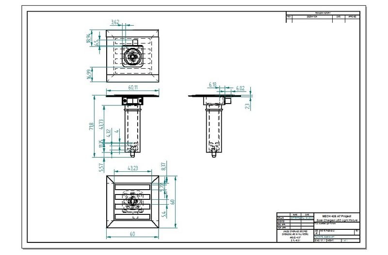
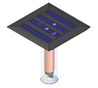
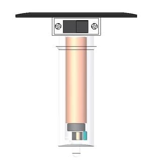
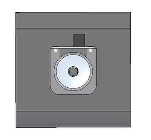
The assembled final product can be seen in Figure 5 and the dimensioned engineering specs can be seen in Figure 6.
Figure 5: Final LED Fixture Design
| Ortho View | Front View | Bottom View |
|---|---|---|
|
|
|
Figure 6: Assembly Dimensions
Installation Into Bottle[edit | edit source]
Installing the light fixture is very simple.
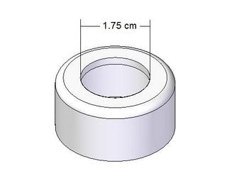
- Cut a 175 mm hole in the center of the recycled pop bottle cap using a sharp knife
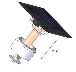
- Insert the end of the assembled fixture through the hole (through the top of the cap)
- Push it in until it reaches the lip approximately 3/4 of the way up the housing
- Force the lip through the hole and stop when the housing is completely inserted into the cap
- Thread the cap with the fixture installed onto the top of the bottle to complete the luminaire
- If the bottle is top heavy, which may happen in tall or small diameter bottles, it can be inverted to rest on the solar cell
Figure 7: Cap and Bottle Assembly
| Cut 175mm Hole | Push Fixture Through Cap | Screw Assembly onto Bottle |
|---|---|---|
|
|

|
Prototype[edit | edit source]
A prototype was constructed in order to demonstrate a simplistic methodology utilizing minimal capital and maximizing the use of recycled materials. This ideology presents some major problems in that recycled materials are not always the correct size and do not always come together into an optimal design. It is a fair price to pay in order to minimize the overall cost and maximize the practicality of the design.
In this case, the parts attained were not exactly to specification, but worked anyway. For example, the recycled ferrite toroid ring is much larger than required, but no other parts were available. The leads for the recycled resistor and LED were very short, making soldering difficult. New parts will make the construction process much more efficient.
Circuit Construction[edit | edit source]
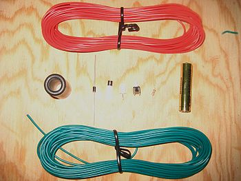
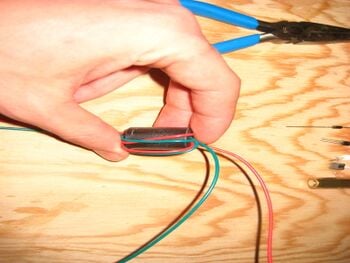
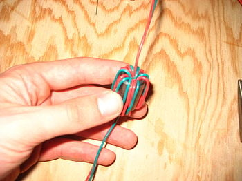
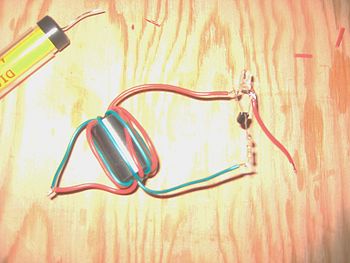
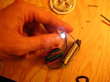
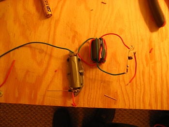
The first step to constructing the prototype is to make the internal circuit. To help simplify the process, a helpful walk through for the construction of the voltage booster portion of the circuit can be seen HERE. The visual steps can be seen in Figure 8 and is followed by a step by step walk through.
Figure 8: Prototype Circuit Construction
| 1. Required Parts | 2. Ferrite Ring | 3. Inductor |
|---|---|---|
|
|
|
| 4. Transistor, Resistor, LED | 5. Battery Test | 6. Diode |
|
|
|
Construction Walk through:
Tools Required:
- Soldering Iron
- Solder
- Needle Nose Pliers
- Side Cutters
Walk Through:
- Twist together one of the pair of ends of the wires selected for the inductor portion of the circuit (see picture 2)
- Pull the twisted end through the center of the ring and continue to feed the wires through, wrapping the ring in the wire pairs. (see picture 2 for the partially completed inductor and picture 3 for the final product)
- Solder one of the blue wires to one of the red wires, leaving the solder and wire ends exposed
- Solder on of the remaining wires to the 1K resistor and clip the remaining lead off
- Spread the two exterior leads on the transistor apart and bend the middle lead backwards
- Solder the middle lead to the lead on the resistor and clip the remaining lead off
- Bend the leads on the LED outward
- Solder the LED leads to the remaining transistor leads (one LED lead to one transistor lead)
- Solder the remaining wire from the inductor to the lead opposite to the flat side of the LED (see picture 4)
- Solder a small section of wire to the remaining lead of the LED, stripping both ends (this will act as the battery contact)
- Connect the battery by connecting the small section of wire from the LED to the positive end of the battery (do not solder, simply test the circuit by touching the lead), and the soldered ends of the inductor wire to the negative end of the battery (this end can be soldered)(see picture 5) (hint: I utilized a recycled battery housing in order to be able to easily connect to the battery electrodes)
- Solder the diode (white striped end closest) to the positive battery lead (see picture 6)
- Solder a wire extension to the remaining diode lead (this will act as the positive solar panel connection)
- Solder another wire extension to the negative lead of the battery (this will act as the negative solar panel connection)
The circuit assembly can now be installed into a suitable bottle cap and bottle.
Cap Assembly Construction[edit | edit source]
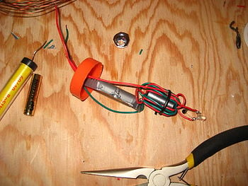
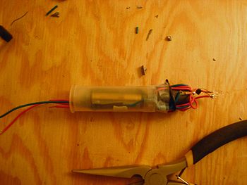
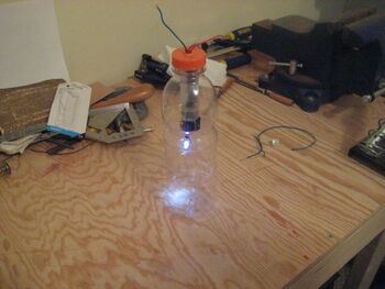
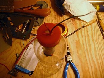
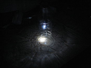
This portion of the prototype is open to customization because each bottle and circuit housing situation will be very different. The visual steps to constructing the bottle fixture can be seen in Figure 9 and is followed by a step by step walk through.
Figure 9: Cap and Bottle Prototype Assembly
| 1. Cap Size Test | 2. Housing Installation | 3. Cap Installation |
|---|---|---|
|
|
|
| 6. Cap Wiring | 5. Lighting Test | |
|
|
Construction Walk through:
Tools Required:
- Sharp knife
- Cut proof gloves
- Glue (can be substituted by cutting larger hole)
- Tape
- Circular housing for the circuit (I utilized a tape core, but the part can easily be substituted)
Walk Through:
- Inspect the cap and neck opening of the bottle to ensure that the circuit assembly can be easily fit through (see picture 1)
- Cut a small hole in the center of the cap for the wires if you have glue, or cut a large hole to suspend the housing if you do not have glue
- Insert the wiring assembly into the selected housing, making sure to feed the two solar panel wires and connection leads through (the connection leads will be connected to a switch) (see picture 2)
- If you have glue: Apply glue to the top side of the housing and install it on the inside of the cap. If you do not have glue: Slide the round housing through the hole in the cap (it should be a tight fit)
- The next steps are not shown in the pictures because I was not able to obtain a functional switch or solar panel in time for the end of this project
- Solder the switch to the two switch leads protruding through the bottle cap
- Glue the switch to the side of the cap if you have glue, or pressure fit it if possible
- Solder the positive and negative solar panel wires to the corresponding leads on the solar panel
- Glue or attach the solar panel to the top of the cap
- Screw the assembly onto the bottle (see pictures 3 and 4)
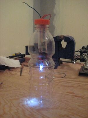
- Turn off the lights in the room and test the light fixture (see picture 5)
The final product (unlike the final design in Figure 9 which is missing the solar panel and switch) is a self sustaining indoor and outdoor solar LED light fixture. It is important to note here that the design outlined here has not been tested in a completed form with the PV. It can be recharged daily by leaving it in the sun during peak daylight hours. The total battery capacity is 1000 mAh when new, which at a draw of 15 mA, will last up to 67 hours, so the light will not need to be charged every day. Make sure not to leave the assembly in the rain as it is not waterproof.
Economic Considerations[edit | edit source]
The custom designed fixture will require very high investment in the short term, but if mass produced, costs could be reduced drastically, making it a viable solution. The prototype solution has lower initial costs, but buying individual parts for each reproduction could be more expensive than mass producing a design. An economic feasibility analysis will be performed in order to determine which is more feasible over the long term.
Custom Designed Fixture[edit | edit source]
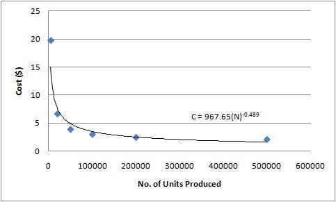
This portion of the economic analysis has been based on the paper [Early Cost Estimation for Injection Molded Parts][21] produced by Dr. O. Kazmer. The paper presents a valid model for predicting the overall production costs involved in tooling and producing injection molded parts, such as the housing portion of this design. He also generated a Java Applet that calculates individual unit costs based on the number of parts produced,[22] which I used as a general model to predict costs over several production stages. The plot of the model can be seen in Figure 10.
Figure 10: Cost Model Plot
The same assumptions and part costs used in the initial circuit analysis have been applied to this analysis, with the addition of the Kazmer cost model and the results are as follows:
| Number of Units Produced | 1 | 100 | 1000 | 10000 | 100000 |
|---|---|---|---|---|---|
| 967.65 | 102.73 | 33.47 | 10.91 | 3.55 | |
| 1.20 | 1.20 | 1.20 | 1.20 | 1.20 | |
| Total Parts Cost / Unit ($) | 6.72 | 3.36 | 1.68 | 0.84 | 0.42 |
| Total Cost / Unit ($) | 975.15 | 107.29 | 36.35 | 12.95 | 5.17 |
The economic analysis spreadsheet for the ideal design can be seen here: File:Mass Production Economic Analysis.xls
The resultant costs in the last row of Table 5 indicate that the final product will become extremely affordable when production exceeds 10000. The closest comparable product on the market sells for almost $25 ,[4] so the costs of $12.95 / unit at 10000 produced, and $5.17 / unit at 100000 produced are very reasonable. If mass production is undergone, and up to 100 000 are made, the final cost of $5.17 plus any additional profit margin markups will be much cheaper than the prototype cost which includes the initial circuit cost of $8.67 (labor included) + any additional part costs associated with construction.
Prototype[edit | edit source]
This portion of the design requires a much more simple cost analysis that is almost identical to the wiring cost analysis with the addition of the assembly parts cost. Most of the parts that I used were recycled, but I am going to consider a worst case scenario where all parts must be purchased (excluding the bottle and bottle cap which must be recycled). The entire construction and assembly process required 30 minutes but I was not being paid (and neither will someone else if they are making it themselves) so labor costs will not be included in the analysis.
| Component | Cost ($) |
|---|---|
| Circuit | 6.57 (labor subtracted from quoted cost) |
| Wiring | 0.15 |
| Solder | 0.05 |
| Housing | 0.50 |
| Bottle + Cap | 0.00 |
| Total Cost / Unit | 7.27 (without labor) |
The cost analysis spreadsheet for the prototype can be found here: File:Prototype Cost Analysis.xls
The total cost per unit is higher than the mass production final cost (at 100 000), but will be much more affordable in the short term. The prototype solution requires very little overhead investment and will provide a suitable, reliable lighting solution. The fixture will have a shorter life cycle than the mass produced option due to construction inconsistencies and potential quality shortcomings of poorly soldered connections. The reduced overhead cost does however justify this chance of quality reduction.
Discussion[edit | edit source]
The main goal of this Mech425 project was to design a simple, cost effective indoor light source that can be used in areas of the world that do not have access to electricity or safe lighting at night. The design utilizes a recycled bottle and cap (with a cap diameter equal to or greater than that of a 2L pop bottle) as a portable, durable platform for a high efficiency LED lighting system that is charged using a small solar panel. The final design had to comply with the functional requirements of minimal cost, maximum simplicity, minimal maintenance, maximum self sufficiency, minimal environmental impact and maximum ease of use.
These requirements led to the choice of a voltage boosted, single AAA, solar charged circuit design that would be applied in either a mass produced, or individually produced housing assembly. Both options come with distinct advantages and disadvantages. Mass production offers very high quality control of parts and assembly, along with minimal parts and labor costs, but only comes with a reduced unit price when high numbers are made. Individual, prototype style production comes with higher parts cost with reduced quality but offers a simple design that can be replicated at a relatively low cost by individuals; thus maximizing simplicity of production. In order to fulfill the ideology of developing a simple, cost effective light source that can be used in areas of the world that function without electricity; the 'prototype' style design would be most appropriate. This option allows the builder to customize the light fixture depending on available parts and tools. This final prototyped design totals a cost of $7.27 for parts, assuming that the builder will not be paid to assemble the unit and all required tools are available.
If funding is provided, the mass production option is viable with a final unit cost of $5.17. This is a much more economically suitable solution for developing nations compared to similar products on the market right now which can cost up to $55.00. The main conclusion that can be deduced from this project analysis is that appropriate solutions, with minimal cost, for problems in developing countries can be easily solved by switching our mindsets from profitable designs to minimal cost designs. It has been proven in this design that a serious problem can be solved with an investment of less than $10.00. These lessons should be applied to engineers and designers everywhere in order to shift mindsets and make a difference in the world.
If there are any questions or concerns, feel free to contact me --S. Gennings 01:53, 31 March 2010 (UTC)
Future Work[edit | edit source]
- Discussion of charge controller
- Build full prototype with PV
- Optimize sizing of PV and LED components
References[edit | edit source]
- ↑ Appropedia, "LED Lighting", https://www.appropedia.org/LED, Accessed March 23, 2010
- ↑ Marktech Optoelectronics, White LED's, http://www.marktechopto.com/Engineering-Services/white-leds.cfm, Accessed March 24, 2010
- ↑ Theledlight.com, "Technical Information", http://www.theledlight.com/LED101.html, Accessed March 23, 2010
- ↑ 4.0 4.1 Barefoot Power, "Barefoot Power", http://www.barefootpower.com/, Accessed March 20, 2010
- ↑ Simply Brilliant, LLC, "Sollight",http://web.archive.org/web/20130320113706/http://www.sollight.com/products/lc200.cfm, accessed March 20, 2010
- ↑ Cosmos Ignite Innovations, "Mighty Light", http://web.archive.org/web/20170806125717/http://www.cosmosignite.com:80/product-brief.htm, Accessed March 20, 2010
- ↑ A. Seigel, "Energy Cool: Lighting up the developing world, http://web.archive.org/web/20131129025635/http://www.huffingtonpost.com:80/a-siegel/energy-cool-lighting-up-t_b_201954.html, Accessed March 23, 2010
- ↑ 8.0 8.1 Sebitosi A.B., Pillay P., New Technologies for Rural Lighting in Developing Countries: White LED's, Cape Town University c2007, Accessed March 23, 2010
- ↑ Linverter, "Linverter- Run four superbright white LED from one or two 1.5v batteries", Accessed March 24, 2010
- ↑ Z. Kaparnik, Make a Joule Thief, Accessed March 24, 2010
- ↑ EDN, "1.5V battery powers white LED driver, http://web.archive.org/web/20081121221924/http://www.edn.com/article/ca454645.html, Accessed March 24, 2010
- ↑ 12.0 12.1 12.2 12.3 China.org.cn, "Average salary increase of urban workers rises to six year high, http://web.archive.org/web/20200309011824/http://www.china.org.cn/government/central_government/2008-04/02/content_14111192.htm, Accessed March 25, 2010
- ↑ 13.0 13.1 13.2 Hotock Group, "4x NIMH AAA 1.2V", http://cgi.ebay.ca/4-PCS-Rechargeable-AAA-1000-mAh-1-2V-NI-MH-NIMH-Battery_W0QQitemZ260571034826QQcmdZViewItemQQptZLH_DefaultDomain_0?hash=item3cab3e74ca#ht_3890wt_1009, Accessed March 25, 2010
- ↑ 14.0 14.1 Digi-key Corp, DIODE SCHOTTKY, http://ca.digikey.com/1/1/369732-diode-schottky-70v-15ma-d0-35-1n5711.html, Accessed March 25, 2010
- ↑ 15.0 15.1 Anticsonline, 10 Pack Expo DPDT Slide Switch, http://www.anticsonline.co.uk/1154_1_1311617.html, Accessed March 25, 2010
- ↑ 16.0 16.1 PCToys.com, "5mm White LED (4 Pack)", http://www.pctoys.com/840556011286.html, Accessed March 25, 2010
- ↑ ebay, 4V 60mA 0.24W solar panel PV solar power 2.4v battery, Accessed March 25, 2010
- ↑ Radioshack, 1K ohm 1/4 Watt Carbon Film Resistor,http://www.radioshack.com/product/index.jsp?productId=2062343#, Accessed March 25, 2010
- ↑ Digi-key Corp, "TRANS NPN LN 30V 100MA BC549", http://parts.digikey.com/1/parts/1003194-trans-npn-ln-30v-100ma-92-bc549.html, Accessed March 25,2010
- ↑ ebay, 2V 70mA 0.14W solar panel PV solar power PCB panel, Accessed March 25, 2010
- ↑ Kazmer, O, Early Cost Estimation for Injection Molded Parts, Accessed March 30, 2010
- ↑ 22.0 22.1 Kazmer, O. Java Injection Molding Cost Estimator, http://web.archive.org/web/20130317083451/http://kazmer.uml.edu/Software/JavaCost/index.htm, Accessed March 30, 2010


