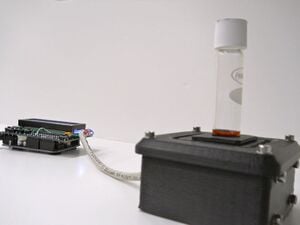
该项目详细介绍了一款开源色度计,它由开源电子设备和 3D 可打印组件制成。这是一个更大项目的一部分,该项目旨在使用开源硬件降低科学设备的成本。[1]
来源
Anzalone GC、Glover AG、Pearce JM。开源色度计。传感器。2013年;13(4):5338-5346。doi:10.3390/s130405338开放获取
摘要
历史上复杂的研究相关传感器和工具的高成本限制了它们只能被一小部分资金充足的研究人员采用。本文提供了一种应用开源方法来设计和开发色度计的方法。讨论了一种仅利用开源硬件和软件解决方案以及现成分立组件的 3D 打印开源色度计,并将其性能与商用便携式色度计进行了比较。使用为封闭回流化学需氧量 (COD) 方法制备的商业小瓶来评估性能。这种方法将可靠的封闭回流 COD 的成本降低了两个数量级,使其成为绝大多数潜在用户的经济替代方案。该开源色度计表现出良好的再现性,并可作为进一步开发和推导其他类似用途(例如比浊法)的设计的平台。这种方法使得最需要的实验室、欠发达国家和发展中国家的实验室能够前所未有地获得基于低成本传感器的复杂仪器。
关键词
开源;开源硬件;比色计;化学需氧量;阿杜伊诺;再现说唱;3D打印机; 开源传感器;化学需氧量;开源色度计
介绍
比色分析方法可能是测定溶解物质浓度最常用的方法。许多溶解的物质吸收特定波长的光,并且当光穿过给定长度的溶液时吸收的量随着物质浓度的增加而增加;较高的浓度比较低的浓度吸收更多的光。吸收和浓度之间的关系由比尔-朗伯定律定义[2]。
使用比色计或分光光度计来测量特定波长下的吸收率。通常对光进行过滤,仅允许处于所测量物质的吸光度峰值波长的窄带光。该装置通常以浓度单位报告结果,但也报告吸光度单位或透射率。
设计文件:http://www.thingiverse.com/thing :45443
固件: http: //github.com/mtu-most/colorimeter
物料清单
- Arduino Uno
- Adafruit LCD 扩展板 ( http://www.adafruit.com/products/772 )
- LED 峰值约为 606nm(如:LEF3833 http://www.jameco.com/Jameco/Products/ProdDS/333665.pdf)
- 适合您选择的 LED 的电阻
- TSL230R 光频传感器
- 原型板(例如:http ://radioshack.com/product/index.jsp?productId=2102845&znt_campaign=Category_CMS&znt_source=CAT&znt_medium=RSCOM&znt_content =CT2032230)
- 导体(Cat 5 电缆效果很好)
- 黑色 ABS 或 PLA 灯丝
- 12 个 M3 螺钉(任意长度;10-12 毫米即可)
- 12 个 M3 螺母
- 20个M3垫圈
指示
- 打印零件并清理它们,以便一切都很好地组合在一起。将 M3 螺母推入箱体每个角的相应槽中 - 槽向内部开放。
- 将原型板切割成一定尺寸(约 27 毫米 x 46 毫米)并钻孔以匹配外壳侧面的孔。
- 用几个螺钉将板松散地连接到外壳内部,然后将比色皿支架推入到位(无盖),并标记传感器和 LED 必须放置在板上的大致位置,以与比色皿中的窗口对齐持有者。
- 从外壳中取出电路板,然后将组件焊接到各自电路板上的标记点上。将 LED 引线留长一点,以便可以移动它以将光束瞄准穿过孔。
- 根据原理图焊接导体。(如果你小心的话,io 引脚可以直接焊接到 LCD 护罩上,否则将需要不同的方法,例如不将护罩用作护罩。)
- 将板装回机箱中,这次要牢固。
- 在Arduino上下载并安装固件。
- 安装 LCD 护罩并为设备供电(适当电压的剩余壁挂电源或 USB 电源即可工作)。
- 将比色皿支架放回原位(无盖)并使用菜单系统选择“校准”。LED 将亮起几秒钟 - 确保大部分光线尽可能直接穿过比色皿支架窗口并照射到传感器上。如果 LED/传感器高或低,请使用小鼠尾锉或适当尺寸的钻头重塑比色皿窗口。
- LED 正确对准后,拆下比色皿支架,然后用四个 M3 螺钉和垫圈将盖子对齐并固定到外壳上。
- 将比色皿支架推入盖子上的开口,并检查盖子是否很好地装入凹槽中。
- 遵循适当的校准协议(尚未内置到固件中 - 即将推出)。
应用领域
媒体
- Joshua M. Pearce,“开源 3D 打印让您可以打印自己更便宜的健康设备”,Conversation,2014 年 2 月 28 日。
- 实验室中的 3D 打印- Biolegend
也可以看看
参考
- ^ Pearce, Joshua M. 2012。“使用免费的开源硬件构建研究设备。 ” Science 337 (6100): 1303–1304。[1]

