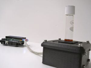
This project details an open-source colorimeter, which is made from open source electronics and 3-D printable components. This is part of a larger project to reduce the cost of scientific equipment using open-source hardware.[1]
Source
Anzalone GC, Glover AG, Pearce JM. Open-Source Colorimeter. Sensors. 2013; 13(4):5338-5346. doi:10.3390/s130405338 open access
Abstract
The high cost of what have historically been sophisticated research-related sensors and tools has limited their adoption to a relatively small group of well-funded researchers. This paper provides a methodology for applying an open-source approach to design and development of a colorimeter. A 3-D printable, open-source colorimeter utilizing only open-source hardware and software solutions and readily available discrete components is discussed and its performance compared to a commercial portable colorimeter. Performance is evaluated with commercial vials prepared for the closed reflux chemical oxygen demand (COD) method. This approach reduced the cost of reliable closed reflux COD by two orders of magnitude making it an economic alternative for the vast majority of potential users. The open-source colorimeter demonstrated good reproducibility and serves as a platform for further development and derivation of the design for other, similar purposes such as nephelometry. This approach promises unprecedented access to sophisticated instrumentation based on low-cost sensors by those most in need of it, under-developed and developing world laboratories.
Keywords[edit | edit source]
open source; open-source hardware; colorimetery; COD; Arduino; RepRap; 3-D printer; open-source sensor; chemical oxygen demand; open-source colorimeter
Introduction[edit | edit source]
Colorimetric analytical methods are likely to be the most commonly applied methods for determining the concentration of dissolved species. Many dissolved species absorb light of a particular wavelength and the amount absorbed as the light passes through a given length of solution increases with increasing concentration the species; higher concentrations absorb more light than do lower concentrations. The relationship between absorption and concentration is defined by the Beer-Lambert law[2].
A colorimeter or a spectrophotometer is employed to measure absorption at a specific wavelength. Light is usually filtered to permit only a narrow band of light at the absorbance peak wavelength for the species measured. The apparatus typically reports results in concentration units but also reports absorbance units or transmittance.
Design files: http://www.thingiverse.com/thing:45443
Firmware: http://github.com/mtu-most/colorimeter
BOM[edit | edit source]
- Arduino Uno
- Adafruit LCD shield (http://www.adafruit.com/products/772)
- LED having peak around 606nm (like: LEF3833 http://www.jameco.com/Jameco/Products/ProdDS/333665.pdf)
- A suitable resistor for the LED you choose
- TSL230R light-to-frequency sensor
- Proto board (like: http://radioshack.com/product/index.jsp?productId=2102845&znt_campaign=Category_CMS&znt_source=CAT&znt_medium=RSCOM&znt_content=CT2032230)
- Conductors (Cat 5 cable works great)
- Black ABS or PLA filament
- 12 M3 screws (just about any length; 10-12mm is good)
- 12 M3 nuts
- 20 M3 washers
Instructions[edit | edit source]
- Print the parts and clean them up so everything fits together nicely. Push M3 nuts into their appropriate slots at each corner of the case body - slots open to interior.
- Cut the proto board down to size (about 27mm x 46mm) and drill holes to match those in the sides of the case.
- Loosely attach the boards to the interior of the case with a couple screws each and push the cuvette holder into place (no cover) and mark the approximate locations where the sensor and LED must be placed on the boards to align with the windows in the cuvette holder.
- Remove the boards from the case and solder the components to their respective boards at the points marked. Leave the LED leads a bit long so it can be moved to aim the beam through the hole.
- Solder the conductors per the schematic. (The io pins can be soldered to directly on the LCD shield if you're careful, otherwise different means will be required, like not using the shield as a shield.)
- Fit the boards back into the case, this time firmly.
- Download and install the firmware on the Arduino.
- Fit the LCD shield and power the device (surplus wall wart of appropriate voltage or USB power will work).
- Place the cuvette holder back into position (no cover) and use the menu system to select "Calibrate". The LED will illuminate for a few seconds - make sure that the majority of light passes as straight as possible through the cuvette holder windows and impinges upon the sensor. If the LED/sensor are high or low, reshape the cuvette windows with a small rat tail file or suitably sized drill bit.
- After the LED is properly aimed, remove the cuvette holder and align and affix the cover to the case with four M3 screws and washers.
- Push the cuvette holder through the opening in the cover and check that the lid fits nicely into recess.
- Follow the appropriate protocol for calibration (yet to be built into the firmware - forthcoming).
Applications[edit | edit source]
Media[edit | edit source]
- Joshua M. Pearce, "Open source 3D printing allows you to print your own cheaper health devices", Conversation, Feb. 28, 2014.
- 3D printing in the lab- Biolegend
See also[edit | edit source]
- Open-source Lab
- Open-source mobile water quality testing platform
- Open-Source Photometric System for Enzymatic Nitrate Quantification
- Open source optics
- Building research equipment with free, open-source hardware
- Open source science
- Open source 3-D printing of OSAT
- Open-source hardware
References[edit | edit source]
- ↑ Pearce, Joshua M. 2012. "Building Research Equipment with Free, Open-Source Hardware." Science 337 (6100): 1303–1304. [1]

