
SDS1104X-E 100Mhz Digital Oscilloscope: FAST


| Bandwidth | Channels | Real time
sampling rate |
Capture rate | Memory depth | |
| SDS1104X-U | 100 MHz | 4 | 1 GSa/s | 4 00,000 wfm/s | 14 Mpts |
Safety Training Requirements
[edit | edit source]- Dr. Pearce Safety Lab Tour
- Worker Health & Safety Awareness
- WHMIS 2015 - Workplace Hazardous Materials Information System
- Laboratory Safety & Hazardous Waste Management
Safety Instructions
[edit | edit source]- Use Proper Power Line: Only the power cord designed for the instrument and authorized by local country could be used.
- Ground the Instrument: The instrument is grounded through the protective earth conductor of the power line.
- Avoid electric shock: please make sure the instrument is grounded correctly before connecting its input or output terminals.
- Connect the Signal Wire Correctly: The potential of the signal wire is equal to the earth, so do not connect the signal wire to a high voltage.
- Look Over All Terminals Ratings: To avoid fire or electric shock, please look over all ratings and sign instruction of the instrument. Before connecting the instrument, please read the manual carefully to gain more information about the ratings.
- Use Proper Overvoltage Protection: Make sure that no overvoltage (such as that caused by a thunderstorm) can reach the product, or else the operator might expose to danger of electrical shock.
- Electrostatic Prevention: Operate in an electrostatic discharge protective area environment to avoid damages induced by static discharge. Always ground both the internal and external conductors of the cable to release static before connecting.
- Avoid Circuit or Components Exposed: Do not touch exposed contacts or components when the power is on. SIGLENT User Manual III Use proper Fuse Use only the specified fuse.
Working Environment
[edit | edit source]Temperature
[edit | edit source]- Operating: 10℃ to +40℃
- Non-operation:-20℃ to +70℃
- Humidity
- Under +35℃:≤90% relative humidity
- +35℃ to +40℃: ≤60% relative humidity
Ventilation
[edit | edit source]- This oscilloscope uses fan to force cooling. Please make sure that the air intake and exhaust areas are free from obstructions and have free air. When using the oscilloscope in a bench-top or rack setting, provide at least 10 cm clearance beside, above and behind the instrument for adequate ventilation.
Care
[edit | edit source]- Do not store or leave the instrument in direct sunshine for long periods of time
Cleaning
[edit | edit source]Please perform the following steps to clean the instrument and probe regularly according to its operating conditions.
- Disconnect the instrument from all power sources, and then clean it with a soft wet cloth.
- Clean the loose dust on the outside of the instrument and probe with a soft cloth. When cleaning the LCD, take care to avoid scarifying it.
SDS1104X-E 100Mhz Digital Oscilloscope
[edit | edit source]- Location: FAST laboratory, Room TEB 06, Thomson Engineering Building, Western University, London, Ontario, Canada
- Vendor: Siglent Technologies [1] [2]
- Name: SIGLENT Technologies North America, Inc
- Address: 6557 Cochran Rd Solon, Ohio 44139
- Phone: Tel: 440-398-5800; Toll Free:877-515-5551; Fax: 440-399-1211
- Email: support
 siglentna
 com
com - Website: siglentna.com
3. Equipment specifications:
- 100 MHz bandwidth
- Real-time sampling rate up to 1 GSa/s
- The newest generation of SPO technology
- Waveform capture rates up to 100,000 wfm/s (normal mode) and 400,000 wfm/s (sequence mode)
- Supports 256-level intensity grading and color temperature display modes
- Record length up to 14Mpts
- Digital trigger system
- Intelligent trigger: Edge, Slope, Pulse Width, Window, Runt, Interval, Time out (Dropout), Pattern
- Serial bus triggering and decoding (Standard), supports protocols IIC, SPI, UART, CAN, LIN
- Video trigger, supports HDTV
- 10 types of one-button shortcuts, supports Auto Setup, Default, Cursors, Measure, Roll, History, Display/Persist, Clear Sweep, Zoom and Print
- Segmented acquisition (Sequence) mode, divides the maximum record length into multiple segments (up to 80,000), according to trigger conditions set by the user
- Automatic measurement function for 38 parameters as well as Measurement Statistics, Zoom, Gating, Math, History and Reference functions
- History waveform record (History) function (maximum recorded waveform length is 80,000 frames)
- 128 k pts FFT, supports Peaks and Markers
- Math functions (FFT, addition, subtraction, multiplication, division, integration, differential, square root)
- Large 7 inch TFT LCD display with 800 * 480 resolution
Calibration & Tolerances
[edit | edit source]Calibration and Due date for calibration
[edit | edit source]Calibration should be done after 180 days past the Date of Calibration" on the certificate with the unit and after each calibration interval.
- Date tested at Factory: 2022-09-27
- First time use: 2023-03-26
- Date of next calibration: 2023-03-26+ calibration interval= 2024-03-26
Self Calibration
[edit | edit source]The self-calibration program can quickly make the oscilloscope reach the best working state to get the most precise measurement values. You can perform self-calibration at any time especially when the change of the environment temperature is up to or more than 5 ℃. Make sure that the oscilloscope has been warmed up or operated for more than 30 minutes before the self-calibration.
Do the following steps to do self calibration:
- Disconnect all the input channels.
- Press the Utility button on the front panel and then press the Do Self Cal softkey.
- Press the Single button on the front panel to perform the self calibration program. During the calibration, most of the keys are disabled.
- When the self calibration program is finished, it will pop-out the message ―press Run/Stop key to exit‖. Press the Run/Stop button on the front panel to exit the calibration interface.
Function Inspection
[edit | edit source]- Press the Default button on the front panel to restore the instrument to its default configuration.
- Connect the ground alligator clip of the probe to the ―Ground Terminal‖ under the probe compensation signal output terminal.
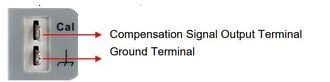
Compensation Signal - Use the probe to connect the input terminal of CH1 of the oscilloscope and the Compensation Signal Output Terminal‖ of the probe.
- Press the Auto Setup softkey.
- Observe the waveform on the display. In normal condition, the display should be a square waveform as shown in the figure below:
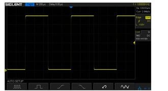
Function inspection


Probe Compensation
[edit | edit source]When the probes are used for the first time, you should compensate the probes to match the input channels of the oscilloscope. Non-compensated or poorly compensated probes may cause measurement inaccuracy or error. The probe compensation procedures are as follows.
- Set the switch to 10X on the probe.
- Perform steps 1, 2, 3 and 4 of ―Function Inspection‖ in the previous section.
- Check the waveforms displayed and compare them with the following:
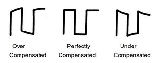
Compensation - Use a nonmetallic driver to adjust the low-frequency compensation adjustment hole on the probe until the waveform displayed is as the ―Perfectly compensated‖ in the figure above.

Operation & Procedure
[edit | edit source]1. Adjust the Supporting Legs
Adjust the supporting legs properly to use them as stands to tilt the oscilloscope upwards for stable placement of the oscilloscope as well as better operation and observation.
2. Connect to Power Supply
The power requirements of the oscilloscope are 100-240 V, 50/60/440 Hz. Please use the power cord supplied with the accessories to connect the oscilloscope to the power source.
3. Power-on Inspection
When the oscilloscope is energized, press the power key at the lower-left corner of the front panel to start the oscilloscope. During the start-up process, the oscilloscope performs a series of self-tests and you can hear the sound of relay switching. After the self-test is finished, the welcome screen is displayed.
4. Connect the Probe
SIGLENT provides passive probes for the oscilloscopes.
- Connect the BNC terminal of the probe to a channel BNC connector of the oscilloscope at the front panel.
- Connect the probe tip to the circuit point to be tested and connect the ground alligator clip of the probe to the circuit ground terminal
5. Run Control
Auto Setup: press this key to enable the waveform auto setting function. The oscilloscope will automatically adjust the vertical scale, horizontal time base and trigger mode according to the input signal to realize optimum waveform display.
Run/Stop: press the button to set the acquisition state to Run or Stop.
- In RUN state, the key is illuminated in yellow.
- In STOP state, the key is illuminated in red.
References
[edit | edit source]“Index of /upload_file/user/SDS1000X-E.” https://int.siglent.com/upload_file/user/SDS1000X-E/ (accessed Apr. 03, 2023).
| Authors | |
|---|---|
| License | CC-BY-SA-4.0 |
| Organizations | FAST |
| Cite as | Motakabbir (2023–2025). "SDS1104X-E 100Mhz Digital Oscilloscope: FAST". Appropedia. Retrieved July 26, 2026. |