
OSHE Growbot Wiring
There are two main electrical systems in the Growbot project; the bot's system and the charging base's system. While developing the two electrical systems, the open source circuit design software KiCad was used to create two wiring diagrams to describe both systems. The first diagram describes all components and connections on the bot. The second diagram describes the interface between the charging base and bot.
Wiring Diagrams
[edit | edit source]-
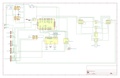 Fig 1: Wiring Diagram for all bot components and connections.
 -
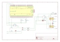 Fig 2: Wiring Diagram for the Growbot bot/base interface.
| Authors | |
|---|---|
| License | CC-BY-SA-4.0 |
| Cite as | Cjhettin (2021–2025). "OSHE Growbot Wiring". Appropedia. Retrieved July 14, 2026. |