
User:Cjhettin

| Name | Christopher (John) Hettinger |
|---|---|
| Affiliations | Michigan Technological University |
| Location | |
| Nationality | |
| cjhettin |
|
| Links | linkedin.com |
| Registered | 2020 |
Hello, I am John Hettinger. I am currently in my third year at Michigan Tech pursuing my B.S. in Computer and Electrical Engineering. I grew up in the Grand Traverse region and I enjoy tinkering with anything I can get my hands on, whether it's computer building or gun restoration.
Interests
[edit | edit source]| Electronics | Computer Architecture | Programming | Building Computers | Robotics | CAD | Hunting | Fishing | Bowling | Video Games |
OSHE (Enterprise Projects)
[edit | edit source]Semester 1 Spring 2021
[edit | edit source]Growbot Base and Laser Break (Circuit Design & Wiring)
[edit | edit source]This semester I was the electrical lead on the Growbot project. One of the things that I worked on this semester was designing a circuit to detect when the bot reached the base to start charging. The goal was to prevent electric shock due to touching the charging prongs attached to the base. I was able to finish the electrical design for the base from the progress made in previous semesters. I was also able to complete most of the wiring for the base, including the power supply, switch box, and IR sensor circuit. However, the charging prongs didn't get printed this semester and neither did the mounts for the sensors. The laser break sensors were tested though, and are confirmed to work with the wire ends that the prongs will be attached to. The code for the Arduino to detect the robot is located in the Github. I also added the base electrical system description to the Growbot Electrical page. Additionally, I started the procedure and materials list for the base and will be finishing them when the wiring for the charging base is completed next semester.
-
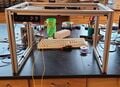 Fig 1: Overall current state of the base.
 -
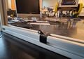 Fig 2: A close up of the current sensor attachment without the mounts.
 -
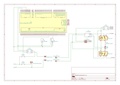 Fig 3: The wiring diagram for the Growbot bot/base interface.


Growbot Bot Electrical (Circuit Design)
[edit | edit source]The other thing that I worked on this semester was modifying the electrical design of the bot to handle autonomous charging. This mainly consisted of the addition of relays to the battery terminals to detect when the bot is receiving power from the base. This causes the bot to switch to a charging circuit with the lipo charger that's mounted inside the robot. Another relay and the raspberry pi handle switching back to the run mode circuit. The circuit is fully designed and the parts are in the lab, but have not been installed or tested yet. I also updated the Growbot wiring page to reflect the most updated wiring diagrams that we have for the project.
-
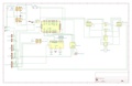 Fig 1: Wiring Diagram that represents all design changes made this semester.
Semester 2 Fall 2021
[edit | edit source]Growbot Base and Laser Break (Circuit Design & Wiring)
[edit | edit source]I stayed on as the Electrical Lead for Growbot during the Fall 2021 semester. At the start of the semester we ran into issues with the laser break circuit. After doing some troubleshooting I concluded that the Arduino Mega 2560 that we were using was faulty. I decided to switch the circuit to use an Arduino Nano V3 instead. I had two reasons for this: 1. The Arduino Nano was working correctly and 2. the Arduino Nano fit better inside the switch box for the base. I also added a 12-25V boost converter between the base PSU and the charging prongs. This change is due to us switching from charging the battery using a LiPo charger to directly charging the battery using a BMS. This means that 25V needs to supplied to the bot instead of 12V. I haven't decided whether to put the boost converter on the base or the bot, but I currently show it on the base in the schematics. Also, some form of current regulation needs to be added as well. This can be done using a different boost converter with constant current control or an external current regulator. Finally I moved the emitter for the laser break to the bot, so the prongs are only energized when the bot arrives at the base and the sensor detects the IR from the emitter on the bot.
-
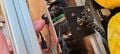 Fig 1: Laser break emitter moved to the bot, waiting for the mount to be printed.
 -
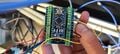 Fig 2: The Arduino Mega 2560 replaced with an Arduino Nano. Used a terminal block mount for easy wiring.
 -
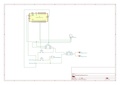 Fig 3: V3 of the wiring diagram for the charging base.


Growbot Bot Electrical (Circuit Design)
[edit | edit source]Regarding the bot's circuit design, I removed the relay switching part of the circuit. Since we're now directly charging the battery using a BMS, we don't need to switch the battery from the 24V rails to the LiPo charger. Instead, we can just connect the charging prongs in parallel to the 24V rail. This way when the charging prongs are energized, the base will charge the battery and also power all components on the 24V rail (which is everything on the bot). Stopping the bot from driving as well as charge detection will be delegated to software control on the raspberry pi.
-
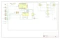 Fig 1: V3 of the wiring diagram for the bot.
OSHE Budget Management
[edit | edit source]In addition to being the Electrical Lead on Growbot, I was also the Budget Manager for the entire enterprise this semester. The primary responsibility that I held was coordinating parts orders between each team within the enterprise, our faculty advisor(s), and the lab supervisor for the ECE department. However, I also designed a budget tracking sheet to keep track of how much each team spends, how much the enterprise spends on lab equipment, and how much money is in the enterprise bank accounts. Finally, I spent the latter half of the semester devising a way to compile orders and submit requisitions on a regular basis. I have created a schedule for the spring and created a Google Form with an accompanying sheet for collecting part orders and making single requisitions for the enterprise as a whole.