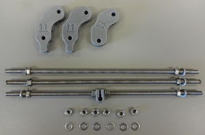
#[[Image:MOST_HSPrusa_frame_3.jpg|thumb|right|Parts for one triangle.]] Put a rod clamp on one rod with a washer and a nut on both sides. Don't screw it tight; you'll need to adjust the position later. Put a nut and a washer on each side of each rod.{{clear}}
#[[Image:MOST_HSPrusa_frame_3.jpg|thumb|right|Parts for one triangle.]] Put a rod clamp on one 370 mm rod with a washer and a nut on both sides. Don't screw it tight; you'll need to adjust the position later. Put a nut and a washer on each side of each rod.{{clear}}
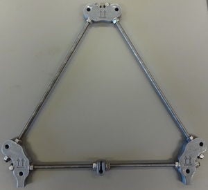
#[[Image:MOST_HSPrusa_frame_2.jpg|thumb|right|Complete triangle.]] Put the trangle together. Make sure the clamp goes between the footed vertices and the feet are both on one edge of the triangle.{{clear}}
#[[Image:MOST_HSPrusa_frame_2.jpg|thumb|right|Complete triangle.]] Put the trangle together. Make sure the clamp goes between the footed vertices and the feet are both on one edge of the triangle.{{clear}}
#Repeat for the other triangle.
#Repeat for the other triangle.
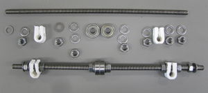
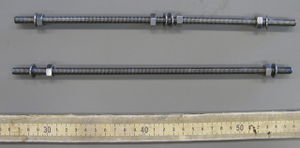
#[[Image:MOST_HSPrusa_frame_11.jpg|thumb|right|Top base rods.]]Assemble the two top base rods, which will go through the top holes of the footed vertices. The image shows the pieces for one rod, and another rod assembled.{{clear}}
#[[Image:MOST_HSPrusa_frame_11.jpg|thumb|right|Top base rods.]]Assemble the two top base rods (440 mm), which will go through the top holes of the footed vertices. The image shows the pieces for one rod, and another rod assembled.{{clear}}
#[[Image:MOST_HSPrusa_frame_7.jpg|thumb|right|Top rods.]]Assemble the top rods.{{clear}}
#[[Image:MOST_HSPrusa_frame_7.jpg|thumb|right|Top rods.]]Assemble the top rods.{{clear}}
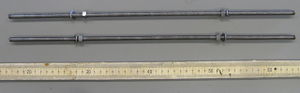
#[[Image:MOST_HSPrusa_frame_6.jpg|thumb|right|Bottom base rods.]]Assemble the bottom base rods.{{clear}}
#[[Image:MOST_HSPrusa_frame_6.jpg|thumb|right|Bottom base rods.]]Assemble the bottom base rods (290 mm).{{clear}}
#Attach the horizontal rods to between the triangles. The bottom frame rod with the nuts and washers on it is the front of the machine. The extruder will be on the left of the top rods, so leave more space there than on the right.
#Attach the horizontal rods to between the triangles. The bottom frame rod with the nuts and washers on it is the front of the machine. The extruder will be on the left of the top rods, so leave more space there than on the right.
Rod clamp (some shown white in the pictures below, but all should be silver)
6
Vitamins
Description
Count
440 mm M8 threaded rod (Top horizontals and bottom of z-axis)
3
370 mm M8 threaded rod (Triangle sides)
6
290 mm M8 threaded rod (Lower horizontals)
4
M8 nut
60
M8 washer
66
M3×12 mm cap screw (Melzi mount)
4
M3 nut
4
M3 washer
4
Assembly - Summary
Assemble triangles
Assemble horizontal rods
Put them together
Assembly - Step-by-Step
Parts for one triangle. Put a rod clamp on one 370 mm rod with a washer and a nut on both sides. Don't screw it tight; you'll need to adjust the position later. Put a nut and a washer on each side of each rod.
Complete triangle. Put the trangle together. Make sure the clamp goes between the footed vertices and the feet are both on one edge of the triangle.
Repeat for the other triangle.
Top base rods.Assemble the two top base rods (440 mm), which will go through the top holes of the footed vertices. The image shows the pieces for one rod, and another rod assembled.
Top rods.Assemble the top rods.
Bottom base rods.Assemble the bottom base rods (290 mm).
Attach the horizontal rods to between the triangles. The bottom frame rod with the nuts and washers on it is the front of the machine. The extruder will be on the left of the top rods, so leave more space there than on the right.