Polarity refers to DC power - one of the conductors is positive (+) one is negative (- or 'gnd' or 'ground' on the controller board). Steps where polarity is a consideration are noted - pay close attention and make sure that the positive and negative conductors are in the correct locations before applying power to the printer! Consequences of failing to observe polarity are expensive.
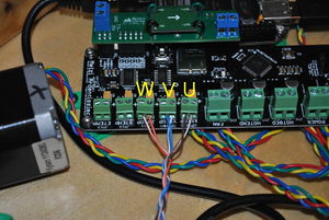
There are three motors that control the movement of the printer. The motors are identified as U, V and W. When looking at the front, the extruder drive (with the fourth motor) is at the back of the printer. The U motor is on the left front, the V motor is on the right front and the W motor is in the back center on the apex with the extruder drive.
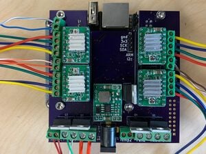
The Athena Board has motor controllers and limit switches labeled for both Cartesian (x, y, z) and Delta (u, v, w) printers.
Procedure
Mounting Electronics
Loosen all of the screw terminals on the Athena Board and insert a small screwdriver into each terminal and wiggle it around to insure that it is fully open. This will greatly ease insertion of wires in later steps.
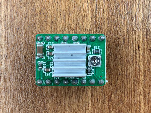
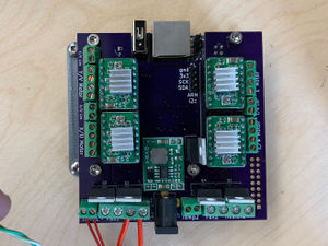
Affix heat sinks to motor controller chipRemove the adhesive backing paper from the heat sink and affix the heat sink to only the chip on the motor controller boards. Note that the heat sink is NOT touching the soldered pins on the side of the board. There is the potential for a short circuit to occur if it is allowed to touch the pins - avoid this!
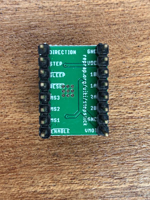
Note orientation of 1B, 1B, 2B, 2A labels.Look at the back side of the motor controller and note the pins having the labels 1B, 1A, 2A, and 2B. These pins must be on the same side as the motor screw terminals on the Athena Board when inserted in their sockets.
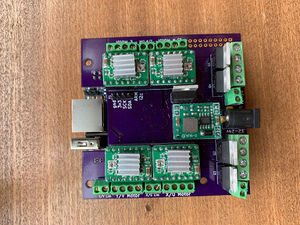
Insert the motor controllers in their sockets. ORIENTATION MATTERS! Failure to properly orient the controllers can lead to destruction of the entire electronics package!Recalling the pins having the labels 1B, 1A, 2A, 2B, insert the motor controllers so those pins are on the same side as the motor screw terminals. Failure to properly orient the motor controllers can lead to destruction of all of the electronics!
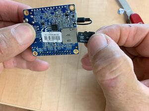
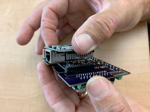
Insert the microSD card.Insert the microSD card into the Orange Pi Zero, contacts go towards the board.
Press the Athena Board onto the Orange Pi.Insert the pins on the Orange Pi into their mating sockets on the Athena Board. Only one orientation is possible, but it is possible to miss a pin on one end or the other. Assure all pins are in a socket! Damage to the Orange Pi can result if misaligned when power is applied.
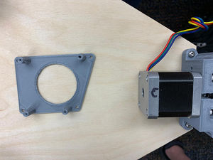
Attach the Athena Board mount to the base in the orientation shown.Refer to picture: With the four #6 x 1/2" sheet metal screws, attach the Athena Board mount to the underside of the base in the orientation shown - note location of the W motor with respect to the Athena Board Mount.
Attach Athena Board to mount.Attach the Athena Board to its mount using the four M3 x 6mm screws. A single orientation is possible.
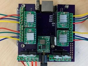
Wire the hot end.Insert the heater cartridge wires into the Heater1 screw terminal and tighten the screws; there is no polarity concern. Insert the thermistor wires into the Temp1 screw terminal and tighten the screws; polarity is not a concern.
File:AthenaII wire fan.JPGWire the fan.Note the color of the wire attached to the red wire on the fan; this is the positive wire. Insert the positive wire into the right side of the Fan1 screw terminal and the other wire into the left and tighten the screws. Polarity matters!
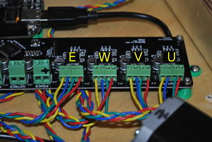
Wire the Motors.The motor wires must be correctly paired in the screw terminals; red-green must be in adjacent terminals and blue-yellow in the other two. Select an order (e.g., red-green-blue-yellow) and follow it with each of the motor screw terminals.
Wire the limit switches.Note the color of the wires on each of the limit switches. Wire the U limit switch to the X/U limit switch screw terminal; V to the Y/V screw terminal, and W to the X/W terminal.
Controller Power and Jumper Settings
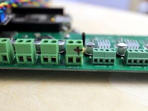
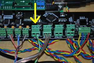
Mark the POSITIVE terminal on the Melzi.Locate the supply power terminals in the center Melzi board (marked POWER). Clearly mark the POSITIVE terminal (the terminal nearest the E-MOTOR terminal) with a permanent marker.
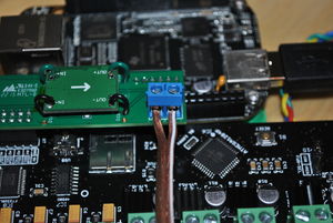
The Melzi power source jumper is in the middle of the board.Set the shorting block so the VREG pins are shorted as shown in the picture.
Wiring
Set the printer on a chair so that the motor end faces upwards. When looking down at the motors, W, U, and V are in clockwise rotation with W being the motor on the apex having the extruder drive and spool holder mounted to it.
Wires can be tucked behind the controller board and secured to the standoffs with wire ties to keep things neat. Secured and well bundled wires are less likely to get entangled and pulled out of terminals.
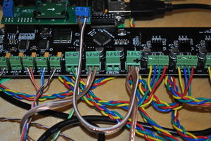
Follow the wiring carefully - click on picture to zoom in.Wire the motors as shown in the image, wiring the drive motors for U, V and W to X-MOTOR, Y-MOTOR and Z-MOTOR, respectively (see photo - note that connecting two motors to the wrong terminals will result in mirrored prints). The extruder motor is likewise connected to the controller to the terminal marked E-MOTOR. If motor leads are colored differently than shown, identify connected pairs of motor wires by touching the conductors together and noting if additional force is required to rotate the motor shaft. Wire pairs that increase resistance to rotation should occupy adjacent terminals (e.g. the pairs shown in the picture are red-green and blue-yellow).
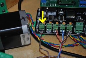
Connect limit switches.Connect the limit switch conductors to their respective axes e.g. the limit switch above the U motor is attached to the U limit switch (marked XSTOP), etc. There is no polarity concern.
Wire hot end thermistor.Connect the hot end thermistor to its respective connectors on the controller board (marked ETEMP). There is no polarity concern.
Wire hot end resistor.Connect the hot end power resistor to its respective connector (marked HOTEND) on the controller board. There is no polarity concern.
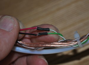
Note the color of the 24ga wire soldered to the red (POSITIVE) wire of the fan - brown-white in this picture.Note the color of the 24ga wire soldered to the red (POSITIVE) wire of the end effector cooling fan.
Attach fan - Polarity matters.Polarity matters! Connect the fan to its terminal on the controller board (marked FAN); red (POSITIVE) wire of the fan to the positive terminal. If the fan does not turn on when the extruder exceeds 50°C, you likely have the wires reversed. The fan can be damaged if this is left to continue for too long.
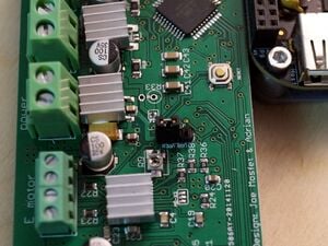
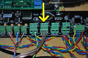
Attach power cable to bridge board - POLARITY MATTERS!.Polarity matters! Reversing polarity at this step will likely result in destruction of the Beaglebone upon application of power. Attach the 15cm (6") long speaker cable to the bridge board screw terminal nearest the screw terminals on the Melzi (see photo) taking note of the markings on the conductors and which terminal (positive or negative) each conductor is attached to. Tighten the screws.
Attach power from barrel connector socket to Melzi and bridge board. Melzi and bridge board are connected in parallel.Polarity matters! Reversing polarity at this step will likely cause destruction of both the Melzi and the Beaglebone upon application of power, producing about $100 worth of smelly, blue smoke. Connect both of the POSITIVE conductors from the barrel connector socket and the bridge board to the POSITIVE terminal on the Melzi. Connect both NEGATIVE conductors from the barrel connector socket and the bridge board to the NEGATIVE terminal on the Melzi. The Melzi and bridge board are connected to the barrel connector socket in parallel. Flattening the wires with pliers followed by trimming their widths greatly facilitates this step.


