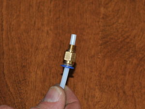
Insure that the sheath fits through the quick connect.Push one end of the sheath (PTFE tubing) into the quick connector and ensure that it passes all the way through the connector. It should fit snugly but not require much force to insert. Remove tubing after checking fit.
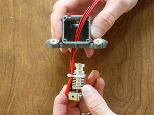
Feed wires through fan opening. Feed the wires through the large opening in the base of the effector and and then through the fan opening.
Aligning hot end with slot.Align the hot end in front of the slot in the end effector. The hot end may need to be rotated to fit.
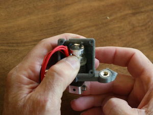
Pressing hot end into slot. Push the hot end into the slot - considerable force is necessary, use a tool against the hot end if necessary. If the hot end slides in easily, it may need to be epoxied in place as it will move around during printing, causing noise in the print.
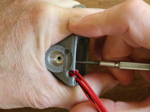
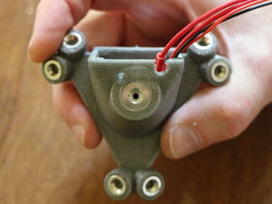
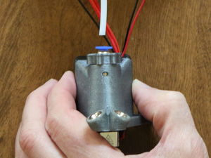
Look through top to check alignment.Check that the hot end is fully seated by looking through the top of the end effector; the entry to the hot end should be centered as shown in the picture.
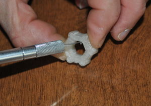
Clean thumbscrew.Clean thumbscrew.Prep a thumbscrew attachment and press it onto the hex portion of the quick connect. Push it all the way to the plastic quick connect ring.
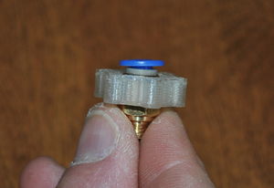
Thread on the reamed quick connector. Thread the quick connect fitting into the top of the hot end. While tightening, hold the hot end, not the end effector.
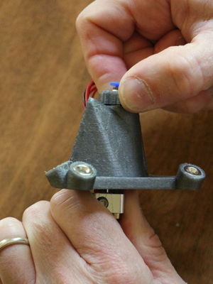
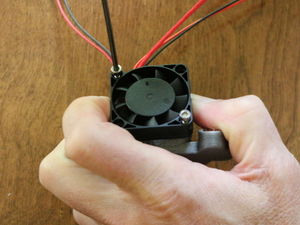
Attach fan to the end effector.Only two M3 x 12mm screws are required to affix the fan to the end effector: Place the fan over the opening with the wires exiting the fan towards the top of the effector and the fan spider (the part that usually has a sticker on it) facing the interior of the effector so that the fan is blowing air into the end effector (some fans have arrows embossed in the case indicating rotation and airflow direction). Align the fan's mounting holes with the holes in the fan opening and plastiform M3 x 12mm screws into opposite corners of the fan.
Push tubing into quick connectPush the Bowden sheath (PTFE tubing) all the way into the quick connect fitting. Use a piece of sand paper to provide a better grip on the slick PTFE tubing. The tubing must be pushed fully into the quick connect or filament will not feed properly.
Secure the fan, thermistor and heating resistor wires to the Bowden sheath with a small wire tie immediately above the Bowden sheath opening.


