
Use Li-ion Batteries Instead of Alkaline

| Manufacturing files | https://www.thingiverse.com/thing:4023136 |
|---|---|
| Hardware license | CERN-OHL-S |
| Certifications | Start OSHWA certification |
| Type | |
|---|---|
| Authors | Dan Brinks |
| Status | Designed Prototyped |
| Years | 2019 |
| Made | Yes |
| Replicated | No |
| Cost | USD 1.37 |
Use (recycled) Lithium Ion Batteries instead of Alkaline (AA, AAA, C, etc) for consumer electronics. Electric/electronic devices, designed to run on 3 volts (traditionally 2 AA, AAA, C, D alkaline batteries), are quite prolific around the world. Some devices are troublesome to swap batteries on - the time/date must be re-set, or they may be in a difficult to access location. Some devices are designed to operate on 3 volts minimum, and don't work well at all on the 2.4v output from a pair of traditional rechargeable batteries. In this case, users are forced to continue buying and discarding/recycling single-use alkaline batteries. Alternatively, the device may be replaced, with one that works better on rechargeable cells. Either route here results in material being discarded, likely ending up in a landfill.
I propose to use rechargeable lithium ion batteries, in place of traditional alkaline, NI-MH or NiCd cells. Lithium ion cells boast a very high power density, storage efficiency, and a low self discharge rate. This makes this ideal to power many electronics already existing around the world. Some circuitry must be added, as the maximum voltage of a standard Li-Ion cell is ~4.2 volts, which could cause problems or even destroy some electronics. Also, Li-Ion batteries do not tolerate being discharged beyond a certain threshold - usually about 2.5 volts. We'll also add a cell protection circuit to prevent the charge from going below critical.
Finally - brand new Li-Ion cells are available on the market - but they are more expensive than traditional alkaline cells by far. For this project, we'll use cells recycled from an old laptop battery pack. Often, when laptop battery packs age or fail, some cells will degrade much faster than others. Even if a pack is completely nonfunctional (in a laptop), often some individual cells within the pack still have useful life. The packs can be carefully disassembled, and individual cells charged and tested. For this project, we'll use "18650" Lithium Ion cells, that were harvested from a non-functioning 2007-era laptop.
Bill of Materials
[edit | edit source]Non-Printed Components
[edit | edit source]These components are needed in this design:
| Quantity | Name | Description | Unit cost (USD) |
|---|---|---|---|
| 2 | Spring type battery connectors | Steel spring style battery connectors are preferred, for ease of use and reliability. These are inserted and soldered to in the 3D printed 18650 cell holder. They're available from many sources, with a name like "Metal Batteries Spring Contact Plate". Alternatively, purchase an individual 18650 cell holder, approx. $0.35 US | $0.04 |
| 1 | Li-Ion protection board | The protection board prevents the Li-Ion cell from being discharged beyond a safe point | $0.19 |
| 1 | 3 volt regulator circuit | This can be done with any standard voltage regulator, and the correct resistors. Recommend a low standby current design - 3volt regulators are available as an assembled PCB from many sources (recommend chip 6206A) | $0.95 |
| 1 | 18650 Li-Ion cell | Try to source this for free, from your (or your friends) non-functional laptop battery, USB power bank, etc. | $0.00 |
| 30cm | Small wire | Wire used for electrical connections | |
| 10g | Solder | A small amount of solder used for electrical connections | |
| 5g | Adhesive | A small amount of epoxy, glue or double sided tape. For mounting circuit boards. | |
| Total: | $1.22 |
Printed design
[edit | edit source]Find the printed design on thingiverse [1] - along with URL for BOM components (appropedia won't let me use ali express links)
This design uses about 7 grams of filament, for a plastic cost of approximately $0.15 US.
Tools needed
[edit | edit source]- MOST Delta RepRap or similar RepRap 3-D printer (OR purchase of 18650 cell holder)
- Soldering iron
- Multimeter (not strictly required, but helpful to check connections)
- Hobby knife, to clean or trim parts, as needed
Skills and knowledge needed
[edit | edit source]- Knowledge of electrical circuits and basic electricity (low voltage)
- Ability to solder wires
- Basic mechanical assembly skills
- Basic mechanical disassembly skills (harvest 18650 cells)
Technical Specifications and Assembly Instructions
[edit | edit source]Print time estimate: 60 minutes
Assembly time estimate: 40 minutes
These instructions will walk you through wiring up the battery terminals to the input of the Li-Ion protection board, and then connecting the output of that protection board to the 3 volt regulator circuit.
- After printing the 18650 holder design, insert metal battery spring clips into each end of the cell holder. The pointed contact end, with the hole for a wire, should be toward the bottom of the cell holder. Bend these metal tails outward, so they're exposed on either end of the battery holder, and can be soldered to.
- Solder short wires to the battery terminals.
- Wires should wrap around, under the battery holder, to a hollow area where the Li-Ion protection circuit can be mounted. Solder the wire from the positive battery terminal to the contact marked B+ (Battery positive) on the board, and solder the wire from the negative battery terminal to the contact marked B- (Battery negative) on the board.
- Power will come out of this board on the P- and P+. Solder 1 short wire to the P+ pad, and 2 short wires to the P- (Ground) pad.
- We'll run these output wires underneath the board, and out the side, where our regulator circuit can be mounted.
- Take one of the P- wires, and solder it to the GND (center) pad on the regulator.
- Solder the wire from the P+ pad to the Vi (Volt in) pad on the regulator.
- Finally, solder a wire to the Vo (Volt out) pad on the regulator - this is the positive output for the circuit. The remaining wire, soldered to P- on the protection board, is the negative output terminal for the circuit.
- Place a charged 18650 battery in the battery case, observing polarity and making sure the battery makes contact with the spring clips in the holder.
- Recommended: Using a multimeter, measure the voltage and polarity on the output terminals. Polarity should be as expected, and you should be getting very close to 3 volts from the circuit.
- Connect the output wires to your consumer device, where the battery would normally go. Look for indications on the battery box for the correct polarity. The negative terminal will usually be a spring, and the positive terminal is often sticks out as a non-moving metal button. You may use solder to secure this connection, or press the conductor securely between the metal connector and the plastic edge, use tape, etc.
- After testing, use an adhesive to secure circuit boards in place. Double sided tape may be a good choice, to mount the 18650 battery holder somewhere on the electronic device it's powering.
Assembly Overview / Demonstration video
[edit | edit source]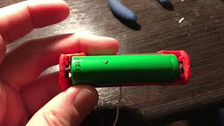
Common Problems and Solutions
[edit | edit source]- Observe polarity for electrical connections! Pay attention to the positive and negative terminals/signs on PC boards/battery - failure to do so could cause damage.
- Depending on the metal battery clip style and plastic thickness, the battery positive terminal may not make good contact, without carving some of the plastic away with a knife.
Cost analysis
[edit | edit source]- Total cost of this design: $1.37 US
- A similar commercial product is about $8 US.
- Printing this design, as opposed to buying from Amazon, yields 580% savings
However - I think it is more appropriate to compare the cost of the above design with what most consumers would be doing, buying and throwing away Alkaline AA cells. A 48-pack of AA cells can be purchased for $14 US, yielding a per-cell price of $0.29. Assuming 2 AA batteries would need to be replaced in a device each year, this design pays for itself in just over 2 years time. If an environmental cost is factored into the production/disposal of alkaline AA's, the payoff time is shorter.
Benefited Internet Communities
[edit | edit source]This design benefits almost any community that has:
- Access to laptop batteries that are being discarded.
- Ability to charge these batteries.
- The desire to operate consumer electronics, without the need for disposable batteries.
As an example, this design benefits the Michigan Tech (Houghton, MI) community.
| Authors | |
|---|---|
| License | CC-BY-SA-3.0 |
| Organizations | MTU, Michigan_Tech's_Open_Sustainability_Technology_Lab, MY4777 |
| Cite as | Dlbrinks (2019–2024). "Use Li-ion Batteries Instead of Alkaline". Appropedia. Retrieved July 24, 2026. |