
Open-source laser system for polymeric welding


This page describes how to make an open source laser system for polymeric welding. For directions on how to use the one located in the MOST lab see: Laser welding protocol: MOST.
Our primary interest in it is making heat exchangers by welding together layers of inexpensive polymers. This is counter intuitive, but our latest theoretical and early experimental results show that this type of heat exchanger can be very efficient as well as absurdly cheap. See: expanded microchannel heat exchangers for our latest paper. These heat exchangers can be used for all kinds of energy efficiency applications including our work to make solar powered water pasteurization systems. If we can get a system that works it will represent an extremely inexpensive method of pasteurizing water at the family or household scale.
If you use the system for other applications please let us know what they are. Happy making!
Mechanical Parts List
[edit | edit source]
The projected dimensions are to be 1.5 ft. by 1.5 ft. This laser welding system was derived from http://www.thingiverse.com/thing:11653 Please start there for understanding the basics of the mechanical setup. The variations we made included the following:
- We mounted the whole system in a double drawer file cabinet that we hollowed out, put on a safety switch for the laser, and new drawers with magnetic closers. A hole was drilled through the top for the wires and the fiber laser to pass through.
- We extended the legs past a square bottom to allow for the cabinet rails to remain intact as seen in the photo.
- We added a second substrate layer that slides in consisting of a metal (Al) substrate and a lower iron glass cover plate (again see details to the right). A source for high transmitivity glass: SGG DIAMAN - Saint-Gobain Glass Vision Product Family -Extra clear low-iron glass.
- We added new 3-D printed parts to couple a fiber laser to the rig. In our case it is hanging down just over the glass with a lens positioned so that the focal point is just under the glass.
Printed Parts
[edit | edit source]- Follow guidelines from http://www.thingiverse.com/thing:11653 and print components.
- In addition you need the specialized components here if you are going to replicate our laser setup: http://www.thingiverse.com/thing:28078
Misumi Parts
[edit | edit source]Stockdrive
[edit | edit source]| Part Description | Part Number | Link |
|---|---|---|
| 18 Teeth Polycarbonate Timing Pulley | A 6T16M018DF6005 | https://sdp-si.com/eStore/PartDetail.asp?Opener=Group&PartID=42977&GroupID=347 |
| Fiberglass reinforced Neoprene Toothed Pulley Belt | A 6Z16MB89060 | https://sdp-si.com/eStore/PartDetail.asp?Opener=Group&PartID=70713&GroupID=342 |
Electronics
[edit | edit source]Electronic parts
[edit | edit source]- Arduino MEGA 2650 - https://www.sparkfun.com/products/11061
- Adafruit Motroshield - http://adafruit.com/products/81
- 6x SN754410 H-Bridge Motor Driver - https://www.sparkfun.com/products/315
- 2x Aavid Heat Sink http://www.alliedelec.com/search/productdetail.aspx?SKU=70115208
- 2x Adafruit Stepper Motor - https://www.adafruit.com/products/324
- 2x Opto Endstop - http://web.archive.org/web/20130124025709/http://store.makerbot.com:80/electronics/electronics-kits/optical-endstop-v2-1-kit.html
- Power Supply with 5 and 12V (e.g. used computer power supply)
- 2x (or more) 12V Computer Fans
- MAX3323 chip (or similar) - http://www.digikey.com/product-detail/en/MAX3323EEPE%2B/MAX3323EEPE%2B-ND/1701884
- 4x 1uf capacitors
- Female Serial-Breadboard cable
- Hookup wire
- Fiber Laser. For the details on our laser see: Laser welding protocol: MOST
- JDSU Fiber Coupled-Diode Laser L4-9897510-100M - http://web.archive.org/web/20150506125656/http://www.jdsu.com:80/en-us/Lasers/Products/A-Z-Product-List/Pages/diode-laser-9xx-nm-fiber-coupled-10w-6398-l4-series.aspx
- LaserMount 264
- TECSource 5305
- LaserSource 4320
- Firmware: https://sourceforge.net/projects/lasersystemforp/
- For software description see: Laser welding protocol: MOST
Electronics Build and Communication Setup
[edit | edit source]- Wiring up the electronics
-
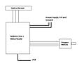 Electronic circuit schematic
 -
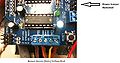 Remove the power jumper! Arduino and motor shield.
 -
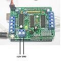 12V and GND
 -
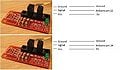 Opto Endstops connections
 -
 Setting boundary with endstop
 -
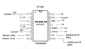 MAXIM 3323E pin assignment
 -
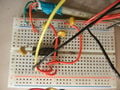 Breadboard Layout with MAXIM chip
 -
 DB9 Female Cable Front View
 -
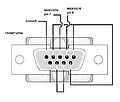 DB9 Female Cable pin assignment


- The jumper near to the GND pin must be removed, otherwise the Arduino will be damaged!
- Connect the 12 V cable to M+ pin and Ground to GND pin on the MotorShield.
- If using Adafruit stepper motors, connect the wires following the order: from M1 to M2, brown, green, skip Gnd pin, yellow and red. From M4 to M3 brown, green, skip Gnd pin, yellow and red.
- Connect the Opto Endstops as shown.
- Fix the Endstops such that the laser carriage reaches the lower left corner of the mechanism.
- Connect MAX3323E pin 1 to a 1uF capacitor, an 1uF capacitor between 1 and 3, another between 4 and 5, and the last 1uF capacitor to pin 6, as shown in the figure. Pin 7 and 8 go to the DB9 cable pins 3 and 4, pins 11,12,13,14 and 16 to 5V and pin 15 to Ground. Pin 9 to Arduino pin 19 and pin 10 to Arduino pin 18. Ground the capacitors as shown, if using polarized capacitors, make sure to connect the negative sides to ground for the capacitors in MAX3323E pin 1 and 6, pin 3 for the capacitor between 1 and 3 and pin 5 for capacitor between 4 and 5.
- Connect DB9's pins 1 to ground, pin 2 and 5 to pin 9, pin 3 to MAX3323 pin 7, pin 4 to MAX3323 pin 8, and pin 7 to pin 8.
- Upload the firmware to Arduino using adruino software (http://www.arduino.cc/).
- Connect the DB9 cable to LaserSource 4320 RS232 input
Note: Depending on if you use different stepper motors or if your system requires more torque from the motors, this will require more current to be supplied from the motor drivers. Replacing the stock Adafruit motor drivers with a SN754410 H-Bridge motor driver will increase the current from 0.6A to 1A. In cases where a lot of torque is required, the drivers can be stacked by soldering the same pins together. Make sure to use a heat sink (Aavid Heat Sink) and thermal paste to aid heat transfer otherwise the driver will overheat. A cooling fan is highly recommended. CAUTION: This is not the best method of increasing current and appropriate precautions should be taken to reduce thermal failure.
-
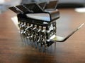 Motor driver chip stack

Safety
[edit | edit source]The Laser is composed by three main devices: LaserMount 264, TECSource 5300 and LaserSource 4320. The LaserMount 264 is a united that integrates a Peltier cooler for precise temperature control and the laser itself. TECSource 5300 is a temperature controller that needs to be attached with the LaserMount. LaserSource 4320 is a Laser Diode Driver, it controls the laser behavior such as Voltage, Current, PWM Duty Cycles and
On/Off control.
The installation of the LaserSource and the TECSource are very straightforward. After unpacking the units, make sure all packing materials have been removed and nothing obscures the ventilation ports on the side and front of the units.
Change The Voltage Selection to the appropriate value and make sure both devices are properly grounded.
The devices have vent holes on the side and front, do not block these vent holes, or overheating may occur, causing damage to the unit.
Connect the cables from the TECSource and the LaserSource labeled LASER and TEC to the LaserMount properly.
To power up the unit, connect the AC power cord to the unit, turn the power switch, located on the front panel, to the on (I) position. The unit will display the model, serial number, and firmware version, go through a quick power-up self-test, and return to the last known operating state.
In order to achieve the highest level of accuracy, the TECSource should be powered on for at least one hour prior to taking measurements.
Once devices are powered up, it is necessary to enable the External Fan Control on the TECSource menu options. Make sure the temperature controller current limit is set to a maximum value of 7.4A.
General Basic Precautions:
The LSO shall be notified of the purchase of any laser, regardless of the class. Such notification should include the classification, media, output power or pulse energy, wavelength, repetition rate (if applicable), special attachments (frequency doublers...etc.), beam size at the laser aperture, beam divergence and users.
No attempt shall be made to place any shiny or glossy object into the laser beam other than that for which the equipment is specifically designed.
Eye protection devices which are designed for protection against radiation from a specific laser system shall be used when engineering controls are inadequate to eliminate the possibility of potentially hazardous eye exposure (i.e., whenever levels of accessible emission exceed the appropriate MPE levels.) This generally applies only to Class IIIB and Class IV lasers. All laser protective eyewear shall be clearly labeled with optical density values and wavelengths for which protection is afforded.
Skin protection can best be achieved through engineering controls. If the potential exists for damaging skin exposure, particularly for ultraviolet lasers (200-400 nm), then skin covers and or "sun screen" creams are recommended.
HANDS - Most gloves will provide some protection against laser radiation. Tightly woven fabrics and opaque gloves provide the best protection.
ARMS - A laboratory jacket or coat can provide protection for the arms. For Class IV lasers, consideration should be given to flame resistant materials.
Theoretical Laser Power Requirements
[edit | edit source]| Material | Spot size (mm) | Laser power (W) |
|---|---|---|
| Polymer | 1 | 10 |
| Polymer | 0.3 | 1 |
| Polymer | 0.1 | 0.1 |
| Al | 1 | 1000 |
| Al | 0.3 | 100 |
| Al | 0.1 | 10 |
If the material is plastic wrap or aluminum foil thickness, the power required is about three times as much. So basically being able to focus the beam not only can give you smaller channels, but it also reduces the required laser power.
See also
[edit | edit source]- Laser welding protocol: MOST
- Open Source Laser Polymer Welding System: Design and Characterization of Linear Low-Density Polyethylene Multilayer Welds
- Expanded microchannel heat exchanger
- Expanded microchannel heat exchanger: Non-destructive evaluation
- Finite Difference Heat Exchanger Model: Flow Maldistribution with Thermal Coupling
- Design Optimization of Polymer Heat Exchanger for Automated Household-Scale Solar Water Pasteurizer
- open source laser cutter project
- Open Source Polymer Welder Literature Review
- Expanded Microchannel Heat Exchanger: Finite Difference Modeling
- Zhang C, Anzalone NC, Faria RP, Pearce JM (2013) Open-Source 3D-Printable Optics Equipment. PLoS ONE 8(3): e59840. doi:10.1371/journal.pone.0059840 open access
- Design, fabrication, and testing of a polymer expanded heat exchanger for absorption chilling
| Authors | |
|---|---|
| License | CC-BY-SA-3.0 |
| Cite as | Bmtymrak (2011–2025). "Open-source laser system for polymeric welding". Appropedia. Retrieved July 13, 2026. |