The open-source rheometer can be used to qualitatively compare the viscosities of various materials. The modifications noted on this page allow the device to be customized to suit the limitations of different research projects at FAST.
Knowing what chemicals are in the lab and how they interact with each other is critical when accidents happen.
Appropriate SDS sheets should be viewed online.
Note the hazards listed on the door to the lab. If you introduce any new equipment or materials you must clear them with the responsible person listed on the lab door. If the responsible person is out of date, contact the departmental administrators to get it updated.
The cup is filled with the fluid being tested, and during each test, the cup rotates and pushes against the loadcell with varying amounts of force.
The rheometer cup is able to rotate because there is a vane placed inside the cup and it is fixed to a metal shaft that is connected to a motor which rotates. Thus, when the motor is spinning, the rotation causes the shaft to spin, and the vane to mix the substance inside the cup. While the motor is running, the speed causes the cup to slightly twist in the direction of the motor rotation (clockwise). The cup is designed to have flexible flexures allowing this movement.
The loadcell was calibrated to read mass in grams and this value is divided by 1000 to be in the SI units of force (kg⋅m/s^2) in the Excel templates (on OSF). By multiplying the mass by the acceleration due to gravity (9.81m/s^2), the force is measured.
Torque is the rotational equivalent of linear force, and is determined as: Torque (N ⋅ m) = 𝑟 𝐹 sinθ, where 𝑟 is the lever radius between the rheometer cup and the loadcell, 𝐹 is the force applied to the loadcell and sin θ is the angle between F and the loadcell lever. The loadcell lever is directly perpendicular to the force being applied to it, so sin90=1. Since this value is 1, it was not added to the torque calculations.
The Arduino is collecting a mass reading for different revolutions per minute (RPM). In Excel, the RPM reading is multiplied by 2𝜋 and divided by 60 to get the rotational rate in radians per second: Rotational rate = (2𝜋/60) × RPM
Viscosity is the measure of a fluid’s resistance to force (Pa⋅s), shear stress is the force, and shear rate is the rate at which deformation is applied: Viscosity = Shear stress / Shear rateShear stress = Torque / [ 2𝜋 × (vane radius2) × (vane length) × ( 1 + ((2 × vane radius) / (3 × vane length)) ) ]Shear rate = [ 2 / ( 1 – (vane radius / cup radius)2 ) ] × Rotational rateFor the original device, the vane radius is 0.01m, the vane length is 0.05m, and the cup radius is 0.015m
When assessing non-Newtonian fluids, the changes in flow behaviour and viscosity are dependent on the force applied. The Arduino testing code for the device collects loadcell data for when the material is being sheared at 60 RPM, 40 RPM, 25 RPM, 16 RPM, 10 RPM, 4 RPM, 1 RPM, 0.6 RPM, 0.1 RPM, 0.04 RPM, and 0.01 RPM.
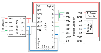
Wire the device according to the diagram, then follow the calibration and operation steps to prepare the device for use.
To calibrate the loadcell, connect the four loadcell wires to the loadcell amplifier, and leave the stepper motor unplugged from the electrical assembly.
Then, the loadcell should be fixed to the loadcell testing mount using the two non-threaded holes so that the ball-point set screw is facing up and hanging off the testing mount.
The loadcell was calibrated to read mass by hanging different weights off of it and reading the outputted data. As a highly sensitive component, the loadcell readings fluctuated around zero by a factor of 1/3745 (or ~0.000267022).
This calibration factor was incorporated into the Arduino code. The calibrated loadcell read the mass of each weight hung off it after being calibrated.
The calibrated loadcell can now be assembled with the rheometer and the motor can be plugged in. The rheometer cup is fixed into the wooden base and sits flush with the loadcell holder to allow the cup to be removed between tests without touching or moving the loadcell (to keep it calibrated).
When the cup is fixed to the wooden base, the mirror tile on the loadcell lever should be making contact with the ball-point set screw on the loadcell. To set up this set screw, start by loosening it so the ball-point is flush with the calibrated loadcell. Then, attach the empty rheometer cup component to the wooden base.
Start tightening the set screw until the ball-point touches the mirror tile. Then, further tighten the set screw by another half turn to ensure the cup is always making contact with the loadcell throughout testing.
Access the Arduino testing codes and Excel templates for the device at the OSF.
Open Arduino IDE, and upload “Code for RPM and Mass Reading” to the Arduino Uno. Open the Excel spreadsheet template for glycerin calibration.
Use the empirical formula to determine the viscosity of glycerin based on the current room temperature. For the original design of parts, 40mL of material is necessary. Thus, enter the room temperature, leave the volume of water blank, and enter 0.04 for the volume of glycerin(in litres). Hit calculate and then input the value for the dynamic viscosity of the mixture into the box for glycerin viscosity on the Glycerin Calibration Excel Template. Save a copy of the file to continue testing.
Add 40mL of fresh, unused 100% glycerin to the rheometer and follow the SOP below for calibrating the device. The entire device is tested using glycerin to determine a calibration factor for the loadcell readings. Instal the motor fixture and ensure all wires are connected. Plug in the Arduino