Bold text
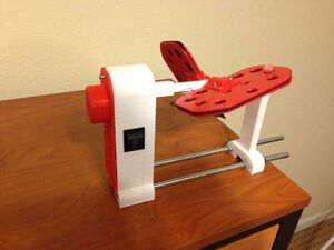
Samle Rotator / Mixer[edit | edit source]
Project developed by Karan
Abstract[edit | edit source]
This Open Source 3D sample rotator accepts a variety of tube sizes and mixes them horizontally, vertically, or any position in between. Changing the mixing angle is easy simply turn the rotisserie. No tools are required.
- Complete 360° rotation
- Adjustable 0-90° mixing angle
- Interchangeable rotisserie options for all common lab tubes.
- Independently adjustable rotisseries Interchangeable rotisseries accept tubes from 1.5 ml to 50 ml.
Each rotisserie is split into two halves. Each of the halves can be exchanged to mix more than one tube type at the same time. Each rotisserie half can be rotated independently from a center point on the shaft. Placing the halves in line with the shaft produces an end over end tumbling motion, similar to that used to mix blood tubes. Rotating the rotisserie at a right angle to the shaft produces a gentle mixing motion, ideal for delicate samples. Any position in between these two extremes may be selected to achieve the desired mixing action. Rotation speed is fixed. - See more at: http://3dprint.nih.gov/discover/3dpx-002349#sthash.y8xvtbiS.dpuf

Cost[edit | edit source]
- Nuts and bolts (all M3 screws and nuts) - Approx $5
- Bearings
- Skateboard bearing: $1
- 5/16 inch ID bearing: $4
- 12V 60rpm Geared Motor: $12
- 9V Battery: $5
- 2 feet threaded rod and 6 nuts: $3
- PLA filament - Approx $8
Total cost : $38
Items to 3D Print[edit | edit source]
All STL files are available here http://3dprint.nih.gov/discover/3dpx-002349#sthash.y8xvtbiS.dpuf
- Small Pillar
- Big Pillar
- Big Pillar Cover
- Motor mount
- Main shaft
- Shaft adaptor
- Wings with embedded adaptors x 4
Instructions[edit | edit source]
- Print all the parts mentioned above.
- After printing pillars, attach the bearings in the space available.(Snap fit should do)
- Screw the motor to the motor mount secure it in the big pillar. Then, pass the shaft adaptor through the other end of the big illar and through the bearing.
- Pass the other end through the bearing on the small pillar
- Slide the o-rings into groves in the main shaft arms
- The rubber pad could be printed with ninjaflex filament to reduce cost even further
- Fit the wings on the main shaft such that the o-rings sit inside the wing adaptors appropriately. Sandwich a rubber pad between them with shape "x" cut on it so that it holds the test tubes well
- Insert the battery into it's slot in the big-pillar
- Pass the three side "ON-OFF-ON" switch through the slot on the big-pillar and then perform soldering with centre pins attached to two battery terminals and the end pins attached to the motor terminals such that one pair of pins is opposite to other pair of pins. This makes the motor rotate in opposite directions when switched in either directions
- Secure the Big Pillar cover with M3 screws running through it
- Make atleast 12 more of these machines for the amount of money you just saved! :)