Background on RF Sputtering System[edit | edit source]
Physical sputtering is driven by momentum exchange between the ions and atoms in the materials, due to collisions.The incident ions set off collision cascades in the target. When such cascades recoil and reach the target surface with an energy greater the surface binding energy, an atom would be ejected, known as sputtering. If the target is thin on an atomic scale the collision cascade can reach the back side of the target and atoms can escape the surface binding energy `in transmission'. The average number of atoms ejected from the target per incident ion is called the sputter yield and depends on the ion incident angle, the energy of the ion, the masses of the ion and target atoms, and the surface binding energy of atoms in the target. For a crystalline target the orientation of the crystal axes with respect to the target surface is relevant.The primary particles for the sputtering process can be supplied in a number of ways, for example by a plasma, an ion source, an accelerator or by a radioactive material emitting alpha particles.[1].More information on the basics of sputtering can be found at;
- http://web.archive.org/web/20130810013458/http://www.allwin21.com/Item.asp?catid=34&id=370
- http://www.perkin-elmer-sputter.com/perkin-elmer-8l-manual-sputter-deposition.htm
- http://www.perkin-elmer-sputter.com/user/image/perkin-elmer-series-4400-and-2400-sputter-deposition-systems.pdf
Applications[edit | edit source]
Equipment[edit | edit source]
| Model 2400 |
|---|
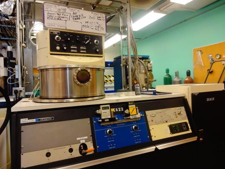 |
The Sputtering System used is in our lab for deposition of metals and ITO films is a 6" Perkin Elmer Model 2400. This is the oldest model of all the sputtering equipment in our labs current. However, it is still capable of high quality uniform films as confirmed by AFM characterization. The tool is available in M&M Room 432 at MTU's Multi-Scale Facility. [2]
To use this tool, prior training leading to qualification is a prerequisite.
Training and Qualification process[edit | edit source]
Information on the qualification process is available at:[3] Or contact Microfabrication Facility Michigan Technological University MFF Director: Bill Knudsen, wknudsen@mtu.edu
Standard Operation Procedure[edit | edit source]
Log On[edit | edit source]
1. Preparation:
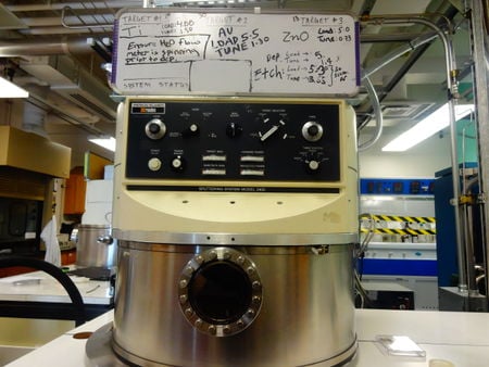
- 1.1 Verify the machine is not in use by another user by checking the white board (see Fig 2), the log book, and the base vacuum status of the machine.
- 1.2 If the system is available to use, write your name on the white board.
- 1.3 Log your name, account number, department, date, and the time into the log book.
| White Board |
|---|
 |
Loading samples in the chamber[edit | edit source]
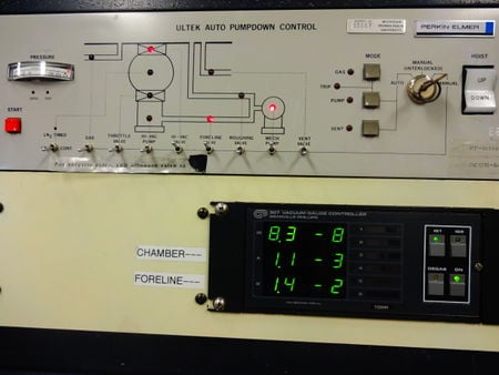
Refer to fig 3 for controls.
2. Vent the chamber from High Vacuum
- 2.1 Turn off the ion gauge by pressing the IG1 button, located in the lower right corner on the front panel of the machine.
- 2.2 Close the Hi-Vac valve by toggling the HI-VAC VALVE switch into its lower position.(DOWN)
- 2.3 Open the vent valve by toggling the VENT VALVE switch to the upper position.(UP)
- 2.4 Wait until the chamber reaches atmospheric pressure. At atmospheric pressure the high pressure gauge will display a pressure of approximately 7.5 x 10² Torr.
- 2.5 Begin opening the chamber by placing one hand over the top base of the chamber and press the Hoist Up button with your other hand.
- 2.6 Insert your samples.
- 2.7 Proceed to close the chamber by pressing the Hoist Down button, making sure to stop and close the VENT VALVE before completely closing the chamber.
- 2.8 Verify that the seal between the chamber top base and bottom base are seated aligned and flush with each other. If the seal is not good, raise the chamber and adjust the top base with the bottom base until the seal is corrected.
Pump Down from Atmospheric Pressure[edit | edit source]
| System Control Panel |
|---|
 |
3. Establish Rough Vacuum in Chamber
- 3.1 Close the chamber.
- 3.2 Close the vent valve by toggling the VENT VALVE switch to its lower position.(DOWN)
- 3.3 Close the foreline valve toggling the FORELINE VALVE switch to its lower position.(DOWN)
- 3.4 Open the roughing valve by toggling the ROUGHING VALVE switch to its higher position.(UP)
- 3.5 Wait for the pressure to reach 5x 10⁻² Torr on the high pressure gauge digital display.
Pump Down from < 50 mTorr to High Vacuum[edit | edit source]
4. Establish High Vacuum in Chamber
- 4.1 Close the roughing valve by toggling the ROUGHING VALVE switch to its lower position.(DOWN)
- 4.2 Open the foreline valve by toggling the FORELINE VALVE switch to its higher position.(UP)
- 4.3 Allow the foreline to evacuate by waiting for the pressure on the foreline pressure display to stabilize.
- 4.4 Open the Hi-Vac valve by toggling the HI-VAC VALVE switch to its higher position.(UP)
- 4.5 When the high pressure gauge indicator reaches 2 x 10⁻³ Torr, turn the ion gauge On by pressing the (IG1) button.
- 4.6 Wait for the ion gauge (IG1) to indicate the base pressure in the chamber has reached 2 x 10⁻⁶ Torr before proceeding to the sputter process. This will take approximately 2.5 h.
Before Sputtering[edit | edit source]
| Water Flow Control Panel |
|---|
 |
5. Initial Preparations
- 5.1 Open the argon tank cylinder located on the back wall of the room.
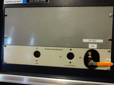
- 5.2 Turn On the water flow by pulling the yellow lever in the lower left corner of the machine DOWN. Ensure the water is flowing through the target head by checking to see if paddle wheel next to the yellow water lever is turning. Refer to Fig 4.
- 5.3 Turn OFF the ion gauge (IG1) by pressing the IG1 button.
- 5.4 Turn On the power supply by toggling the Power On button, located on the Power supply console, upwards.(UP)
- 5.5 Close the throttle valve by toggling the THROTTLE VALVE switch upwards. (Up is close for the throttle valve.)
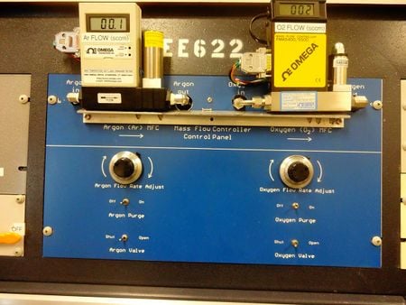
- 5.6 Open the argon gas valve, located on the front panel of machine (fig.5). Set the argon gas flow rate on the MFC controller display to 10 SCCM by tuning the argon flow rate dial.
| Gas Flow Controls |
|---|
 |
Clean the Sample and Target[edit | edit source]
Before the actual sputter deposition one of the following 2 steps to either clean the Sample or clean the Target is usually done.
Pre-Etching (Clean Samples 5 min.)[edit | edit source]
Samples should be cleaned for 5 min to remove any organics that may have built up on its surface. There are four targets plates installed in the sputter system. Three of them have a metal target attached to them. The forth plate does not have a metal target attached to it. The blank forth plate is selected to be face over the table holder with the samples. Plasma is generated between these two plates to clean the samples in the sputter etch process. Note: The Pre-Etch process requires an argon gas flow of 30 SCCM.
6. Pre-Etching Settings
- 6.1 Adjust the argon gas flow to 30 SCCM.
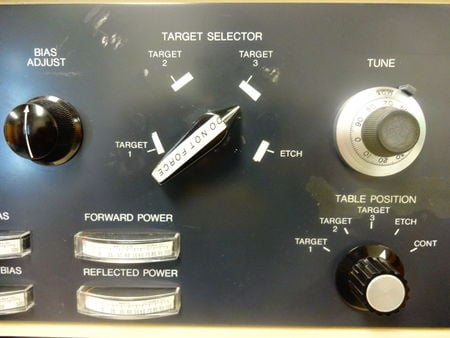
- 6.2 Adjust the knobs on the sputter deposition front panel to the following (See fig 6):
     Set Load = 5.00
     Tune = 3.05
     Mode = Sputter Etch
     Target selector = Etch
     Table position = Etch
- 6.3 Press the white button on the panel to turn the RF power On.
- 6.4 Slowly increase the RF power by rotating the Power Adjust button clockwise and check to see if the plasma is On before stopping at a FORWARD POWER of 50 watts.
If the plasma is on, the TARGET BIAS will be greater than zero and there will be a purple light inside the chamber.
- 6.5 Adjust the Load and Tune values to reduce the REFLECTED POWER and keep it below 10 Watts. Do not allow the FORWARD POWER increase beyond 100 watts. ( The scale on the meter is x 10)
- 6.6 Increase the RF power further up to 100 watts and check to see if the plasma has turned on. If there is no plasma, press the ignition button.
- 6.7 Adjust the Load and Tune values to minimize the reflected power and increase the forward power to a desired level. (usually 100 watts) Retune as needed.
- 6.8 Set and start the timer for the 5 min Pre-Etch.
- 6.9 Reduce the RF power (Power Adjust knob) to zero when the timer runs out.
Pre-Sputter(Clean Target)[edit | edit source]
Targets should be cleaned for 5 min before sputtering to remove any oxides and impurities that may have accumulated on them. The Au target is not to be cleaned.
For the pre-sputtering process, plasma is generated on one side of the chamber to clean the Target while the samples are held on the opposite side of the chamber. Each Target in the chamber has a number associated with it. The number is written on the white board for reference and indicates the Target’s position in the chamber. Set the Target´s Selector accordingly to the desired Target to be cleaned. Always set the TABLE position to be furthest away (180 degrees) from the Target being used. Each target has a starting LOAD and TUNE value, written on the white board, that will be used in the pre-sputter sequence.
7. Pre-Sputter Settings
87.1 Adjust the knobs on the sputter deposition front panel to the following:
     Set Load = Value written on white board next to Target being used
     Tune = Value written on white board next to Target being used
     Mode = Sputter Deposit
     Target selector = Set to the Target you want to clean
     Table position = Set Table opposite Target being used
| Deposition Controls |
|---|
 |
Initiate Plasma=[edit | edit source]
- 7.2 Press the white button on the panel to turn RF power on.
- 7.3 Slowly increase the RF Power by rotating the Power Adjust button clockwise and check to see if the plasma is on before stopping at a FORWARD POWER of 50 watts.
If the plasma is on, the TARGET BIAS will be greater than zero and there will be a purple light inside the chamber.
- 7.4 Adjust the Load and Tune values to reduce the REFLECTED POWER and keep it below 10 watts. Do not allow the FORWARD POWER to increase beyond 100 watts.
(The scale on the meter is x 10)
- 7.5 Increase the RF power further up to 100 watts and check to see if the plasma has turned on. If there is no plasma, press the ignition button.
- 7.6 Adjust the Load and Tune values to minimize the reflected power and increase the forward power to a desired level. (usually 100 watts) Retune as needed.
- 7.7 Set and start the timer for the 5 min Pre-Sputter.
- 7.8 When there is 5 sec left on the timer slowly reduce the Power Adjust knob to achieve a FORWARD POWER of 25 watts.
RF Sputter Deposition (Immediately following Pre-sputtering)[edit | edit source]
8. Deposit on samples
- 8.1 Set the timer to the desired deposition time
- 8.2 Turn and set the TABLE POSITION knob to move your samples under the desired TARGET. Look through the chamber window to see exactly when the Table has moved under the target.
- 8.3 Slowly increase the POWER ADJUST knob to achieve a forward power of 100 watts. If the reflected power is not zero, minimize it by adjusting the Load and Tune.
- 8.4 Start the timer.
- 8.5 Midway through the deposition sequence make note of the high pressure gauge chamber pressure and fill this information into the logbook.
- 8.6 When there is 5 sec left on the timer slowly reduce the Power Adjust knob until it reaches 0.
- 8.7 Set the TABLE POSITION to the ETCH POSITION.
Pre-Sputtering Ti target (5 mins) 1. Set Load = 4.88
Tune = 1.50
Table Position = Target 3
Target Selector = Target 1
Mode = Sputter deposit 2. Power, Power Adjust Sputtering Ti 1. Set Load = 4.88
Tune = 1.50
Table Position = Target 1
Target selector = Target 1
Mode = Sputter deposit 2. Power, Power Adjust Pre-Etching Au target No need for pre-etching. Sputtering Au 1. Set Load = 5.50
Tune = 1.30
Table Position = Target 2
Target selector = Target 2
Mode = Sputter deposit 2. Power, Power Adjust Pre-Sputtering Cu target (5 mins) 1. Set Load = 5.54
Tune = 0.50
Table Position = Target 1
Target selector = Target 3
Mode = Sputter deposit 2. Power, Power Adjust Sputtering Cu 1. Set Load = 5.54
Tune = 0.50
Table Position = Target 3
Target selector = Target 3
Mode = Sputter deposit 2. Power, Power Adjust
After Sputtering[edit | edit source]
9. Finishing Procedures
- 9.1 Turn off the argon cylinder in the back of the room.
- 9.2 Turn the argon gas flow dial down to zero. Close the ARGON GAS VALVE.
- 9.3 Open the throttle valve by toggling the THROTTLE VAVLE switch to its lower position.(DOWN)
- 9.4 Switch the Power supply to OFF.
- 9.5 Turn the water OFF by turning the yellow lever upward.
- 9.6 Turn On the ion gauge (IG1) to check if the base pressure is was maintained after deposition.
- 9.7 Turn OFF the ion gauge (IG1).
89.8 Close the HI-VAC VALVE.
- 9.9 Open the VENT VALVE.
- 9.10 Wait for the chamber to reach atmospheric pressure. Approximately 7.5 x 10² Torr.
- 9.11 Open the chamber and retrieve the samples.
- 9.12 Close the chamber.
- 9.13 Close the VENT VALVE before completely closing the chamber.
- 9.14 Follow the Pump Down procedures.
Log Off[edit | edit source]
10. Sign out of the log book. Log 2.5 h plus the amount of time it took to deposit!!.
- 10.1 Remove your name from the whiteboard.

