


Build guide[edit | edit source]
The complete build guide and all other files related to the project are available for download in the project's repository.
Related Publications[edit | edit source]
- Debbie L. King, Adegboyega Babasola, Joseph Rozario, and Joshua M. Pearce, "Mobile Open-Source Solar-Powered 3-D Printers for Distributed Manufacturing in Off-Grid Communities," Challenges in Sustainability 2(1), 18-27 (2014). open access
Project Overview[edit | edit source]
This is a joint project between:
- Sustainable Energy Applied Research Centre of St. Lawrence College
- Pearce Research Group at Michigan Tech in Open Sustainability Technology
Project created and supervised by:
- SEARC's lead researcher Adegboyega Babasola
- Dr. Joshua Pearce, professor at Michigan Tech
Project Student Research Assistant:
Linked Project(s):
Objective[edit | edit source]
To improve on the design of the original mobile solar powered 3D printer. Build a smaller, more portable charging station, that runs solely on renewable energy for a 3D printer using open source appropriate technology. Update: 23 July, 2012. Two separate models will be designed.
- Model A - will be a ultra-low power model, using an SD compatible RepRap. This will be a small, light model; but will only be able to print parts that have been stored on the SD card.
- Model B - will be capable of new part design in the field.
RepRap Background[edit | edit source]
The RepRap is a low-cost 3D printer, designed by Dr. Adrian Bowyer. It runs on open-source software. And is self-replicating. More information on the RepRap can be found on the RepRap at:RepRap.org/wiki
Model Design[edit | edit source]
Tasks[edit | edit source]
Come up with a design- Choose components
PrinterComputerPanelsBatteriesCharge ControllerInverter (if needed)
Test individual components- Build design
- Test design
Choosing Components[edit | edit source]
The first step of the planning will involve research all of the possible components that will make up the design(s).
Printer[edit | edit source]
The printer choice will determine the size, power consumption, and the amount of customization available. A number of different RepRap models will be considered. A Mendel, running Gen6 electronics is already available for testing power circuits with. The RAMPS circuitry will also be explored. RAMPS is made with open-source Arduino electronics and is very customizable. Other models will be considered, with the criteria being:
- low power consumption
- small in size, or foldable or easily disassembled
- customizable (open-source, available SD card reader, unused i/o pins on board)
- price
- availability
- print quality
One particular printer model that stands out is the FoldaRap. It was designed to fold into a very small size to be completely portable. It is an open-source design, with full build instructions posted by Emmanuel, the creator, and a member of the RepRap community. The FoldaRap could be an ideal candidate for the project. Update: 23 July, 2012. The FoldaRap has been chosen for Model B.
PV Modules[edit | edit source]
It has been decided that this model will run on solar power. All current photovoltaic technology will be examined, to determine the appropriate solution for this project. The main factor in deciding which module to go with, will be portability. The sheer size and weight of the common glass covered panels make them unviable for portable applications. Thin film modules will most likely be used. All of the power drawing components must be chosen for the wattage requirement to be determined.
Batteries[edit | edit source]
In the original mobile solar cart used 4 deep cycle sealed lead acid batteries. They had a combined weight of 400lb, and a volume of over 64,000cm3. This, along with the two bulky panels, was the reason for the cart's extreme size. In this redesign, small battery size and weight will be crucial. Lithium batteries are a clear choice over SLAs. While Li-ion batteries have only approx. 6% higher energy capacity volume-wise, their energy density is much lower, making Li-ions much lighter. Also Li-ion batteries are more stable and therefor easier to transport. The specific type of Li-ion, LiFePo4, or another type of lithium polymer battery is yet to be determined.
Laptop alternative[edit | edit source]
A large part of this design will involve reducing the power consumption of both the RepRap and the devices needed to run it. Running the printer from an average laptop more than doubles the watt hours needed.
| Possible
Solution |
Price | Power
Consumption |
OS | Pros | Cons |
|---|---|---|---|---|---|
| $35 | 3w | Linux | Very cheap, Large online community support,RepRap software available on Linux | Long delivery times,Unknown if processingspeeds are enough to runslicing software | |
| APC 8750 | $49 | 13w | Android 2.3 | Better processor thanRaspberry Pi,Good price | No available softwarewould have to writenew program,Not readily available yet,High power consumption |
| Efika MX Smarttop | $140 | 5w | Linux | Runs Linux,Most processing powerof mini pc options,Already enclosed in housing | Higher cost,has been recently discontinued |
| Efika MX Smartbook | $199 | 0w | Linux | Runs Linux,Battery life of up to 7hso no extra power draw,Wifi & 3G for downloading new designs,lowest cost for highest functionality | Higher cost |
| Control through cellphone via bluetooth | $29 (with exsisting cell) | 0w | Android | Cell phones widespread,cool factor | Current software needs improvement,can only print designs already in hand |
| Use only a SD card slot | $35 | 0w | N/A | ultra low power | can only print designs already in hand,no community design |
| Tablet | $150-500 | 0w | Varies | No extra power drawon system,Readily available, | Higher cost,Unknown if it can run software |
| OLPC | $100-200 | 15w | Linux | Large user community,already scaled in developing world | Expense,difficulty running some softwaresee notes |
| Build OS Micro PC | Unknown | ? | Any | Can build for very low power,Keep cost down by not usingunnecessary components,Will create new Open source, low power/cost PC | More time to build,many unknown factors |
* See Progress Update, August 2nd, 2012 A low-power monitor would be needed in conjunction with the first three options. There are many different models available at prices starting as low as $20. Different monitors would be chosen for each computer, based on available i/o configurations.
Charge controller[edit | edit source]
This is an charge controller circuit designed to charge 4 x 14.8V Li-ion Batteries from 5 20W PV Panels. The output can run any device that can run off 12-16.8VDC that draws less than 20A. Complete power circuit diagram. Corresponding parts list found in Bill of Materials. Click the image for a full size view.

CAD Designs[edit | edit source]


This version was designed to fit in a standard travel suitcase. This increases its ability to be transported to the remote locations that it will be most useful. While the original idea was to put it in a carry-on suitcase, it was decided that with the current state of airport security, the likehood of being allowed to transport this with you on a plane was low. So a standard size suitcase was chosen instead. Figures 6 & 7 show the intended design. The semi-flexible solar panels, and folding reprap fit easily into a standard 24-26" suitcase with plenty of room for the combiner box which will house all of the electrical components, and the batteries. While in the design, the panels are shown uncovered, in reality they will be bundled up with a sturdy canvas fabric that they will be mounted to. The canvas will act as protection during transporting. It will also hold them all together and act as a tabletop for the makeshift panel mounting apparatus that will be used to align the panels in the field.
Bill of Materials[edit | edit source]

To open the original Excel file and have access to the clickable hyperlinks, click File:BOM V2.xls
Progress Updates[edit | edit source]
July 24th, 2012:
- The FoldaRap has been ordered from the maker's crowd funding campaign. Awaiting confirmation from the maker of the power consumption before ordering the other components.
- Currently researching DIY charge controllers (with MPPT) and inverters.
August 2nd, 2012:
- Raspberry Pi tested for viability. Tested board was very glitchy, could not source enough power to run peripherals (ie: mouse, keyboard.)The oscillating quartz crystal was not working properly. Most likely just got a lemon, but from reading the forums, this was not the only one. Because of this, the slow lead times for ordering, and the likelihood that they would not run the needed software anyway, the raspberry Pi will not be used for this project.
- A few different high efficiency MPPT controller circuits have been found. Still awaiting power consumption numbers for the FoldaRap to begin adjusting circuit to meet specific power requirements.
- Exploring the option of designing a bare bones pc to run the RepRap host software, then comparing the prices to buying a SBC (single board computer).
August 7th, 2012:
- After researching many SBCs and finding the average cost to be around $150 for the necessary specs, it was decided to settle on the Efika Smartbook by Genesi. This laptop is $50 more, has the necessary specs, but would not draw any power from the circuit, since it has its own battery life of approx 7 hours. And would not require the purchase of a display. Genesi is a company whose sole focus is making low-power, low-cost computing solutions, geared for developing countries.
August 9th, 2012:
- Batteries and panels ordered. Still unsure of FoldaRap power consumption, so a power circuit was chosen that can run a 60W printer for 6.5h, or up to a 90W printer for 4.3h. Still much longer than the average 2h print.
August 16th, 2012:
- Panels and laptop arrived today. Preliminary testing shows both are working as expected.
August 21st, 2012:
- The batteries arrived last week. Dismantling them revealed a good onboard BMS. Now it will have to be decided whether our system can simply communicate with the current BMS, or whether it will be scrapped and the controller will be used to control the batteries. See Battery Tests for more details.
- It has been decided to base our charge controller design off current open source designs available. The two controllers under consideration are the Free Charge Controller and the Arduino Peak Power Tracker Solar Charger. The Arduino build is a much simpler design, and would therefore be easier to modify to for this projects specific requirements.
August 24th, 2012:
- Printing and slicing software installed on smartbook. Control of a different 3D printer through the computer was successful. Also the slicing (turning a 3D cad file into printable gcode language) was more successful than expected, it only took 2.5min to slice a fairly large printable object. So far the smartbook is meeting and exceeding expectations.
October 29th, 2012:
- Battery connector built, batteries tested, controller circuit designed and parts ordered. Still waiting on printer.
Testing[edit | edit source]
Panel Tests[edit | edit source]
First panel test:
| Spec'd | Measured | |
|---|---|---|
| Voc | 20.6V | 21.02V |
| Isc | 1.38A | 1.04A |
Also tested under a 20.5ohm load and got 18.09V. Will do further testing with a larger selection of power resistors. The short circuit current (Isc) was not as high as spec'd, but the panel was not optimally angled toward the sun. Another test will be performed to gauge Isc. The panels are very light weight, they will be easily transportable. They appear to be quite durable; and they bend to the 30° as advertised (See Fig. 10.)
-
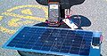
Fig. 8 - Voc test
-
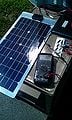
Fig. 9 - Under 20ohm load
-
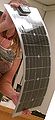
Fig. 10 - 30° bend test


Smartbook Tests[edit | edit source]
The Genesi Efika MX Smartbook comes loaded with it's own unique Linux distribution. It loads fairly quickly, and connected to the nearest unsecured wireless network automatically. The speed is not the best, but as good as expected for it's hardware. It is extremely lightweight, and has very small overall dimensions, even when compared to a 13.5" netbook (See Fig. 11.) Its power consumption is lower than the 12W advertised. Start up: 7-8W Idle (with wireless on): 6-7W Idle (with wireless off): 5-6W Playing a movie(wireless off): 6w Suspended: 1W
-
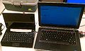
Fig. 11 - Smartbook size comparison

Battery Tests[edit | edit source]
The 14.8V 6600mAh Li-ion batteries, are tested, and are outputting 14.6V. The batteries come with their own battery management system (BMS), which controls the way they are charged, monitors cell levels to avoid over charging or over discharging, and monitors temperature with a thermistor. It is designed to communicate with its specific laptop model via a 7-prong output (See Fig. 12 & 13)

Fig. 12 - Battery connector pin out As per Fig. 12, it was tested that A and B are connected and make up the negative terminal, as F and G are connected and make up the positive terminal.According to the product website the battery uses SMBus for communication. SMBus is a two-wire communication, loosely based off I2C communication. It would be preferred to build a controller that talks to the current BMS that comes with the batteries, as it is already tailored to the specific cells, and will save time in programming, and avoid potential problems and damage to the cells with improper coding. Li-ions charge different from sealed lead acid batteries (SLAs) found in larger solar projects. While SLAs can be charged by simply applying a small constant trickle current until full, Li-ions have up to 3 different charging stages, depending on how far they have been discharged. This required a more complex BMS, which is another reason it would be ideal to keep the current BMS in place.
To connect to the battery terminals, male fast connect tabs were doubled up and secured around the wire with small zip ties (see figures 17 & 18.) During testing phase, the connectors were just inserted into the battery terminals, but once built into the circuit, with the proper circuit protection in place, the connectors can then be soldered to the battery terminals. The batteries were test charged with a high current 17V power supply. 17V was used to simulate the panel voltage. It was found that the onboard BMS was able to properly regulate the current flow, not charging too quickly, which can reduce battery life. This meant that no extra circuitry was needed in the controller circuit to regulate the current fed to the batteries. Also the panels output voltage already matches the batteries expected input voltage, so that meant the only voltage regulation that was needed would be from the batteries to the printer.
-

Fig. 13 - Battery laptop connector
-
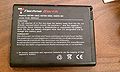
Fig. 14 - Battery case
-

Fig. 15 - Battery inside
-
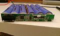
Fig. 16 - Battery Management System
-
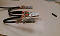
Fig. 17 - Battery connectors
-
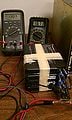
Fig. 18 - Battery test setup


See also[edit | edit source]
- Recyclebot on RepRap wiki
- Mechanical testing of polymer components made with the RepRap 3-D printer
- Development and feasibility of applications for the RepRap 3-D printer
- Solar powered distributed customized manufacturing
- Open source 3-D printing of OSAT
- RepRap PV System Literature Review
- Free Charge Controller
- Arduino Peak Power Tracker Solar Charger
- useful notes in User:C Blair