


Greenboy3D V1 Pellet Extruder Conversion for the Original Prusa i3 MK3S

Introduction
[edit | edit source]This guide documents the modifications required to install and operate the Greenboy3D V1 Pellet Extruder on an Original Prusa i3 MK3S.
It is intended to supplement the official Greenboy3D V1 Assembly Guide rather than replace it. Unless otherwise stated, follow the original Greenboy assembly instructions. This page only describes the steps that differ for the MK3S conversion along with the firmware, CAD files, hardware resources, and testing procedures used during this project. Please read through the entire page before assembling.
Resources
[edit | edit source]Greenboy3D Documentation
[edit | edit source]Greenboy Wiki
https://wiki.greenboy3d.de/docs/Getting%20Started
Contains:
- Original CAD files
- STL files
- Updated documentation
Original Greenboy V1 Assembly Guide
📄 Download the Original Greenboy3D V1 Assembly Guide
Firmware
[edit | edit source]Modified Prusa Firmware
https://github.com/uwo-fast/Prusa-Firmware-GB3DPE
This repository contains the firmware required to operate the Greenboy Pellet Extruder using the Original Prusa i3 MK3S electronics.
Wiring Guide
[edit | edit source]Official Prusa Einsy RAMBo Wiring
https://help.prusa3d.com/article/einsy-rambo-electronics-wiring-mk3-mk3s-mk3s_2107
Use this guide when connecting the
- Heater
- Thermistor
- Fans
- Extruder Motor
- PINDA Sensor
CAD Files
[edit | edit source]Adapter Height Modification + Shim
[edit | edit source]The Edit feature controls the adapter height.
Current value:
6 mm
Changing this extrusion raises or lowers the complete pellet extruder assembly.
PINDA Sensor Assembly
[edit | edit source]Contains the custom PINDA mounting system.
Replacement Components
[edit | edit source]WINSINN 5V Cooling Fans
[edit | edit source]https://www.amazon.ca/WINSINN-40x20mm-Brushless-Cooling Extruder/dp/B07L2YKR7Y
DigiKey Connector Parts
[edit | edit source]https://www.digikey.ca/short/ftjv99d2
Contains
- Connector housings
- Crimp terminals
Assembly Modifications
[edit | edit source]Only the following steps differ from the original Greenboy3D V1 Assembly Guide.
Step 1–2: Adapter Installation
[edit | edit source]Instead of mounting the adapter as shown in the original guide, mount the adapter directly to the Original Prusa MK3S extruder back plate using
- 3 × M3 × 25 mm socket head cap screws
- 3 × M3 hex nuts
Trim the screws to the required length after installation so they do not interfere with the coupler, auger, or any other moving components.
After completing this modification, continue following the original Greenboy assembly guide.
Western University Users
If the screws need to be shortened, the Western Engineering Student Machine Shop can assist.
Alex Nutting
anutting@uwo.ca
📷 Figure 1 – Adapter mounted to the original MK3S back plate
-
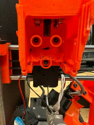 Front view of the adapter mounted to the original MK3S back plate fastened with nuts on the inside.
 -
 Rear view showing the three (M3 × 25) mounting screws.


Step 3: Shim Installation
[edit | edit source]Before attaching the adapter to the motor, install the custom shim between the
- Stepper motor face
- Printed adapter
The shim raises the pellet extruder assembly to correctly align the
- Heat block
- Barrel
- Side mounting screws
The adapter has been designed using a 6 mm height increase, which provides proper alignment with the shim installed.
After installing the shim, continue following the original Greenboy assembly guide.
📷 Figure 2 – Shim installed between motor and adapter
-
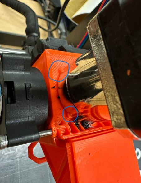 Shim already fixed under the motor and on top of the adapter (Use the screws and nuts provided in the kit to hold everything together).

Step 11: PINDA Mount
[edit | edit source]Install the custom PINDA mount included in the provided CAD files.
Adjust the sensor height during printer calibration until reliable first-layer probing is achieved.
📷 Figure 4 – Installed PINDA Mount
-
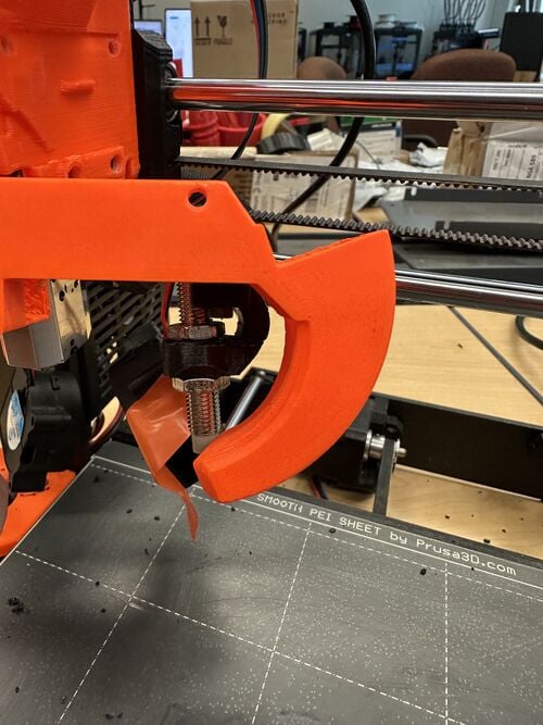 Front View of PINDA sensor attached to Greenboy 3d fan duct.
 -
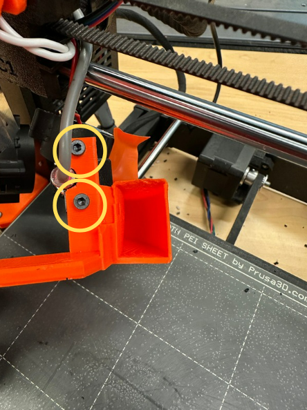 Top View of screws (M3x10) holding PINDA sensor in the Fan duct, use nuts at the bottom to hold the screws in place.
 -
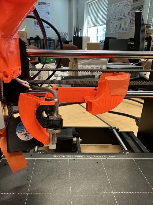 Back View of PINDA sensor in the Fan duct.

.png)
.jpg)
Wiring Modifications
[edit | edit source]The Original Prusa i3 MK3S wiring harness was modified to support the Greenboy3D V1 Pellet Extruder. With the exception of the PINDA sensor, all original hotend wiring was replaced with new connectors and wiring compatible with the pellet extruder assembly.
The original PINDA sensor connector and wiring were retained and reconnected directly to the Einsy RAMBo control board.
The following components received new wiring and connector terminations:
- Pellet extruder stepper motor
- Heater cartridge
- Thermistor
- Hotend cooling fan
- Part cooling fan
All replacement connectors and crimp terminals used during the conversion are available in the DigiKey parts list in the link above. Wire cutters, Wire strippers and the Crimp tool should be available in the lab.
When terminating the new wiring, ensure that:
Connector polarity matches the original Prusa wiring where applicable. Crimp terminals are fully seated within the connector housing. Wiring is routed away from moving components and hot surfaces. Adequate strain relief is provided to prevent wire fatigue during printer operation.
Note: The PINDA sensor retained the original Prusa MK3S connector and wiring and therefore does not require re-crimping or connector replacement.
Cooling Duct
[edit | edit source]The blower duct is sealed using tape.
This is intentional and prevents air leakage around the fan interface, directing airflow through the printed cooling duct instead of allowing it to escape around the housing.
📷 Figure 5 – Cooling duct sealing


Firmware
[edit | edit source]Install the modified firmware available from
https://github.com/uwo-fast/Prusa-Firmware-GB3DPE
The firmware contains the required changes for operating the pellet extruder using the Original Prusa MK3S electronics.
Wiring
[edit | edit source]Follow the official Prusa Einsy RAMBo wiring guide during installation.
Verify the following before powering the printer:
- Heater cartridge
- Thermistor
- Extruder motor
- Part cooling fan
- Hotend cooling fan
- PINDA sensor
Testing
[edit | edit source]It is recommended to test each component individually before attempting a print.
Recommended testing order:
- Heater
- Thermistor
- Hotend fan
- Part cooling fan
- Extruder motor
- X-axis
- Y-axis
- Z-axis
- PINDA sensor
- Homing
- Pellet extrusion
Testing components individually makes troubleshooting significantly easier than diagnosing failures during a print.
Testing using Pronterface
[edit | edit source]Pronterface is an open-source host software that allows direct communication with the printer over a USB serial connection. During development of this project, it was used to verify the operation of individual hardware components, manually send G-code commands, monitor printer status, and diagnose issues before attempting a complete print.
Using Pronterface allows users to isolate electrical, firmware, and mechanical problems without running a full print job. This significantly reduces troubleshooting time when bringing up a new pellet extruder installation.
Some common tasks performed with Pronterface include:
Connecting to the printer through the correct serial (COM) port. Monitoring hotend temperature and heater performance. Sending manual G-code commands. Moving individual axes. Testing the pellet extruder motor. Verifying fan operation. Checking PINDA sensor functionality. Confirming successful homing before printing.
Once all components have been verified individually, proceed with loading pellets and performing the first extrusion and print tests.
Maintenance
[edit | edit source]Cleaning a Jammed Auger
The auger is the rotating screw located inside the pellet extruder. Its primary function is to transport plastic pellets from the hopper into the heated barrel while simultaneously compressing the material. As the pellets move through the heated section of the extruder, they melt and are forced through the nozzle to produce the printed part.
Proper operation of the auger is essential for consistent material flow and reliable printing. Regular inspection and cleaning are recommended to prevent plastic buildup that could reduce extrusion performance or cause the auger to become jammed.
During operation, small amounts of molten plastic can solidify around the auger if the printer is shut down before all material has been extruded or if a jam occurs. This may cause the auger to become difficult or impossible to remove from the heat block.
If the auger is stuck, do not force it out while the extruder is cold, as this may damage the auger, heat block, or surrounding components.
Procedure
1. Remove any remaining pellets from the hopper.
2. Heat the hotend to the normal printing temperature for the material that was last used (for example, approximately 220 °C for PLA).
3. Allow the hotend to remain at temperature for several minutes so that any plastic trapped around the auger softens.
4. Turn off the printer and disconnect the power supply before beginning disassembly.
5. Wear heat-resistant gloves and use appropriate tools, as the heat block and surrounding components will remain hot for several minutes.
6. Carefully separate the auger assembly from the heat block.
7. Remove the softened plastic from the auger threads and the inside of the barrel using a lint-free cloth or a suitable non-metallic cleaning tool.
8. Allow all components to cool before reassembling the extruder.
Warning: Do not touch the heat block or nozzle with bare hands while they are hot. Serious burns can occur. Always wear appropriate personal protective equipment and allow components to cool before handling whenever possible.
After cleaning, inspect the auger for any damaged threads or remaining plastic before reinstalling it. Ensuring the auger is clean will improve pellet feeding and reduce the likelihood of future jams.
-
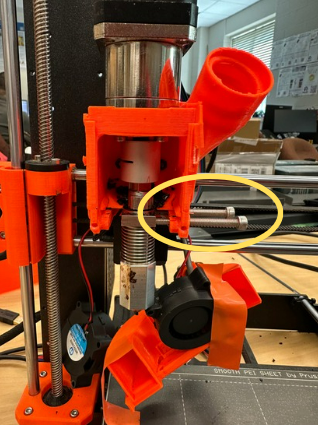 Remove the screws securing the heat block so it is no longer supported. Remove the motor coupler from the top of the auger.
 -
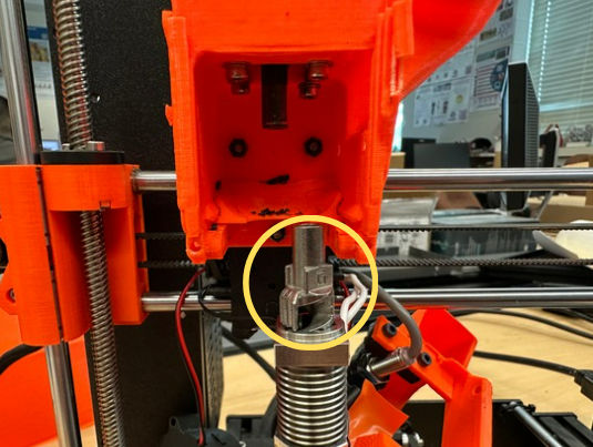 Separate the Auger from the heat block to clean it.


Troubleshooting
[edit | edit source]| Problem | Possible Cause | Solution |
|---|---|---|
| Side screws do not align | Incorrect adapter height | Adjust the Edit extrusion in the CAD model. |
| Heat block sits too low | Shim missing | Install the shim. |
| Heat block sits too high | Adapter too tall | Reduce the Edit extrusion. |
| Poor cooling | Air leakage | Verify the blower tape seal and fan orientation. |
| PINDA not triggering | Incorrect mounting height | Recalibrate the sensor. |
| Extruder not feeding | Coupler or motor issue | Check motor wiring, coupling alignment, and extrusion temperature. |
Gallery
[edit | edit source]📷 Full Assembly Closed

📷 Full Assembly Inside

📷 Front View

📷 Pellet Filled View

Contact & Support
[edit | edit source]Greenboy3D
[edit | edit source]For questions regarding the original pellet extruder design:
Kristian Friesen
Email: kristian@greenboy3d.com
Wiki: https://wiki.greenboy3d.de/docs/Getting%20Started
| License | CC-BY-SA-4.0 |
|---|---|
| Organizations | Free Appropriate Sustainable Technology, Western University |
| Cite as | HaddenC (2026). "Greenboy3D V1 Pellet Extruder Conversion for the Original Prusa i3 MK3S". Appropedia. Retrieved October 8, 2026. |