This page focuses on the Pump'n Power, which is an alternative power generation device designed and created for the Flock House for their 2012 migratory housing habitat project in New York. The needs of the Flock House were identified and criteria were developed to ensure a design that met certain needs and specifications. After multiple alternative solutions were formulated, one solution was chosen which best met the given criteria. A list of costs were cataloged for hours spent and materials used for the project. The final project results are pending the testing results of the new generator. Following the results are a list of simple steps for creating the project.
Background[edit | edit source]
The Pump'n Power was a 12-week project created at HSU as part of the Engineering 215 - Introduction to Design class. The Flock House, led by Mary Mattingly, tasked Team Excergy to design and develop an alternative power generation source to use for their Flock House project in New York. Flock House is an organization that plans for a possible future of living by creating habitats that are mobile. These habitats insert themselves into their surroundings to simultaneously live off of and provide for their environment. Lonny Grafman, the sustainability adviser for the Flock House and teacher of the Introduction to Design class at Cal Poly Humboldt, directed multiple student teams to create a variety of projects to be used for the Flock House. Team Excergy, the designers and creators of the Pump'n Power, was one of those teams. After collaboration with Mary, Team Excergy developed nine criteria to be met and they are as follows: safety, cost, durability, ease of use, transportability, energy output, aesthetics, embedded energy, and educational value.
Problem Statement and Criteria[edit | edit source]
Problem Statement[edit | edit source]
The objective is to create a human powered generator that produces energy in an entertaining and innovative way that may be operated by people of most ages and capabilities.
Criteria[edit | edit source]
| Criteria | Weight | Description |
|---|---|---|
| Safety | 10 | All electrical components safely weatherproofed, all hazardous moving components protected from user. |
| Cost | 10 | Must be less than or equal to $375. |
| Durability | 8 | Must withstand a lifespan of 8 months in New York climate. |
| Ease of Use | 7.5 | Simple, non-intimidating, and no instructions required. |
| Transportable | 7.5 | Mobile enough for one person manage. |
| Energy Output | 7 | Minimum: 50 Watts |
| Embedded Energy | 6.5 | The energy in a material's production and transportation. |
| Aesthetics | 6 | Attractive without compromising safety, durability or cost. |
| Educational Value | 5 | Spreads the idea of sustainability though alternative energy. |
Description of Final Design[edit | edit source]

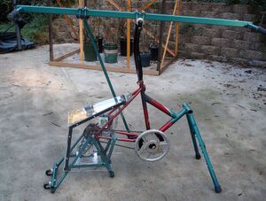
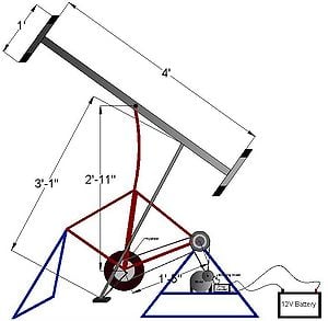
The Pump'n Power utilizes kinetic energy primarily from upper body strength to operate a lever arm, as seen in a railroad hand pump trolley, to produce electrical energy. The lever arm drives a bar connected to the lower portion of a recycled bicycle. The rear tire gear has two chains connected to it. The first is attached from the petal gear to the rear gear, and the second is attached from the rear gear to the generator. The generator is mounted to the lower structure of the bicycle support piece. From the generator a charge controller, along with a blocking diode, are then connected to a battery. The following subsections break the Pump'n Power generator down into its components and explain them in detail.
Components[edit | edit source]
Bicycle[edit | edit source]
The main component of the solution is a bicycle that is available to be stripped, cut, and reassembled in a way that utilizes the bicycle's already manufactured gears, bearings, and support bars.
Gears[edit | edit source]
The gear system for a standard multiple speed bicycle is perfect for a multiple chain generation setup. One side of the pedal setup is an ideally shaped rotating axis to attach the piston shaft to from the lever arm. The gears attached to the pedal create a way to transfer the energy from pumping to the back wheel gear cassette.
Frame[edit | edit source]
Removing the front forks and stripping off the handlebars, wheel, and all braking/shifting components allows for the forks to be inverted and inserted in the location for the seat. This creates an upright support to secure the lever arm as well as supplying us with an already manufactured spinning axle between two supports. As for a lever arm, a square steel bar can be used and a round steel tube can be used as a shaft to run to the rotating pedal. With this design, a triangular base with the gears and chains and a shaft and lever arm setup are created. This also completes the setup for a lever arm generator made mostly from bicycle parts.
-
Bike to modify
-
Gear Setup
-
Modified Frame
-
Lever arm + Frame
Lever Arm[edit | edit source]
The lever arm consists of a metal bar with an old bicycle handle bar attached to each end. The lever arm rests on a rotating axis that was constructed from the front wheel hub of a bicycle. The arm is held in place by two u-bolts that are inserted through two metal rectangles which are welded onto the center of the lever arm. Through this process and axis of rotation is created for the lever arm. Also attached to the lever arm in an almost identical fashion is the unused pedal from the other side of the bicycle. As the lever arm rotates on its axis it powers the lever bar.
-
Lever Arm
-
Pivot Point
-
Handle
Electrical[edit | edit source]
A small generator is attached to the rear gear setup of the bicycle. It then sends its power through a blocking diode to ensure that the current only flows to the battery and not away from it. A charge controller is also used to smooth out the current coming from the system to the battery, and also insures there is no chance of overcharging the battery.
-
Generator setup
Final Design[edit | edit source]
The finished product of the Lever Arm Generator is can be used in two ways. First, small appliances can be directly hooked into the female end of the cable connected to the generator thus powering each item individually. Second, the Lever Arm Generator can be used to charge a battery to store power for later use.
Proper usage of the Lever Arm Generator can be achieved by one or two people by stationing themselves adjacent to the lever bar and applying an up and down force on the lever bar. The lever bar's motion causes the bike portion of the generator to begin rotating due to the connecting shaft between the two components. As the pedal gear rotates, the wheel connected to the rear gear spins causing the belt attached to both the generator and the tire of the wheel to produce power.
-
Final design
Usage[edit | edit source]
The finished product of the Lever Arm Generator is can be used in two ways. First, small appliances can be directly hooked into the female end of the cable connected to the generator thus powering each item individually. Second, the Lever Arm Generator can be used to charge a battery to store power for later use.
Proper usage of the Lever Arm Generator can be achieved by one or two people by stationing themselves adjacent to the lever bar and applying an up and down force on the lever bar. The lever bar's motion causes the bike portion of the generator to begin rotating due to the connecting shaft between the two components. As the pedal gear rotates, the wheel connected to the rear gear spins causing the belt attached to both the generator and the tire of the wheel to produce power.
Maintenance will be needed primarily to ensure that all rotating joints are properly greased and functioning properly.
Costs[edit | edit source]

Design Cost[edit | edit source]
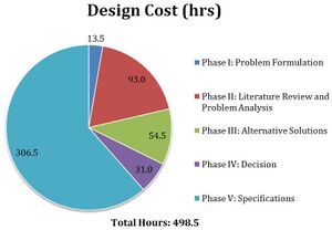
The cost of the design is measured in number of hours, represented in the chart to the right. The chart is distributed by number of hours spend in each phase of the design process. A total of 499 hours were spent in the entire design process.
Implementation Cost[edit | edit source]
Below is a table of the cost of materials used in the construction of the Pump'n Power Handcar Generator. The costs are tabulated in two columns: one indicating items that were donated and of zero cost, and one indicating the projected cost of the donated items. The total cost of implementation the design was: $208.43.
| Material | Quantity | Our Cost Subtotal | Retail Cost Subtotal |
|---|---|---|---|
| Bar, Round, Steel 3/4" x 5' | 1 | $5.51 | $5.51 |
| Bar, Square, Steel 1-1/2" x 6' | 1 | $18.94 | $18.94 |
| Bicycle | 2 | Donated | $120.00 |
| Bicycle Components | Total | Donated | $10.00 |
| Blocking Diode | 1 | $9.45 | $9.45 |
| Charge Controller | 1 | TBA | TBA |
| Chain Tool | 1 | $16.19 | $16.19 |
| Fuse Holder | 1 | $3.23 | $3.23 |
| Fuses, 8A, Pack of 4 | 1 | $3.45 | $3.45 |
| Gear, 13 tooth, splined | 1 | Donated | $5.00 |
| Hand Grips (two sets) | 2 | $24.30 | $24.30 |
| Hardware (nuts, bolts, washers) | Total | $43.80 | $43.80 |
| Hub Axel | 1 | $3.00 | $3.00 |
| Motor, 24V, 350W, 8.9A | 1 | $63.00 | $63.00 |
| Plate, Aluminum, 6" x 6" x 1/2" | 1 | Donated | $10.00 |
| Plexiglass, 3' x 3' | 1 | $4.00 | $4.00 |
| Rectifier, 50V 25A | 1 | $3.77 | $3.77 |
| Spray Paint, Rustoleum Primer | 1 | $4.84 | $4.84 |
| Steel Endcaps | 2 | $2.39 | $2.39 |
| Steel Spacers | 5 | Donated | $5.00 |
| Weight, Disc, 10lb | 1 | Donated | $10.00 |
| Wire, Red and Black, 3' Each | 2 | $2.57 | $2.57 |
| Total: | $208.43 | $368.43 | |
Maintenance Cost[edit | edit source]
Maintenance of the Pump'n Power Handcar Generator is illustrated in the table below, in number of hours per month.
| Maintenance Task | Frequency | Time (hours) |
|---|---|---|
| Inspect and tighten bolts. | Weekly | 0.25 |
| Inspect and oil chains. | Weekly | 0.25 |
| Inspect electrical components for moisture. | Weekly | 0.25 |
| Monthly Total: | 3.00 | |
Results[edit | edit source]
For the final testing of the Pump'n Power device, the generator is hooked up to a multimeter and a light bulb. Two people then pump the lever arm on each side to start the whole process. As the gears rotate, electrical energy is produced and sent through the leads of the multimeter and light bulb. The multimeter is used to measure how much energy is being produced and the light bulb presents a physical representation of energy generated. The exact specifications of the Pump'n Power generator have yet to be determined and are pending the final tests.
How to Build[edit | edit source]
If you would like to build your own, check out the Pump'n Power Handcar Generator instructions.
Discussion and Next Steps[edit | edit source]
Discussion[edit | edit source]
The testing phase first consisted of mechanical testing. This involved dynamics and correcting the lengths and angles of our system. The stability of the base was also part of the testing process in which the team welded support beams where needed. By testing out different lengths of handlebars and shafts we found a fairly decent spot to mount it all together. One big issue involved the mechanical motion of the actual bike crank. The system seemed to have a jump in it when the shaft-side reached the top of its motion. Adding a flywheel solved that problem by providing enough weight to create the momentum needed for better operation. After tuning the mechanical side, electrical testing was the final step. We tested the Pump N' Power on an old car battery. Components we had were a generator, blocking diode, rectifier and charge controller.
Next Step[edit | edit source]
The team hopes to spark interest among the community on the innovative side to electricity generation.
Team Excergy[edit | edit source]
References[edit | edit source]
Pump'n Power Final Document


