
Compact Open Source Automated Monochromator


Introduction
[edit | edit source]Monochromators are light dispersing elements used in various systems to produce a spectrum of light intensities at each wavelength by filtering light source into light beams with narrow bandwidths. Spectrometers are commonly used in conjunction with monochromators. This project has been conducted by Natalie Wieber.
Equipment
[edit | edit source]- Focusing and collimating mirrors
- Diffraction grating
- NEMA 17 stepper motor
- Arduino Nano (with supporting wires)
- A4983 Stepper Motor Driver (with supporting capacitor and power supply)
- PLA and 3D printing capabilities (find OpenSCAD and .stl at https://www.myminifactory.com/object/3d-print-compact-open-source-automated-monochromator-145673)
- M3 x 8 mm hardware
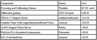
Bill of Materials for this device

Development
[edit | edit source]Geometry
[edit | edit source]
This device employs the crossed Czerny-Turner configuration. Optics Toolbox was used to calculate diffraction angle of various wavelengths, using this equation:
Electronics
[edit | edit source]An Arduino Nano is used to communicate code to the stepper motor driver. Two digital pins connec the Arduino and driver, while a 5V connection enables the driver's microstepping functions. The driver is grounded and connected to a 24V power supply, with a capacitor across the pins. The four motor leads are connected to the driver.
Following is the Arduino code, prompting the motor to take 100 steps in one direction, pause, and take 100 steps in the other direction. When the 5V is connected to microstepping enable ports on the driver, each step is a fraction of a full step, so the 100 steps ideally rotates the motor shaft the range necessary for experimentation:

//define pin numbers
const int stepPin = 2;

const int dirPin = 3;

void setup() {
 // Sets the two pins as Outputs
 pinMode(stepPin,OUTPUT);
 pinMode(dirPin,OUTPUT);

}

void loop() {
digitalWrite(dirPin,HIGH); // Enables the motor to move in a particular direction
 // Makes x pulses
 for(int x = 0; x < 100; x++) {
   digitalWrite(stepPin,HIGH);
   delayMicroseconds(10000);
   digitalWrite(stepPin,LOW);
   delayMicroseconds(10000);
 }
 delay(1000); // One second delay
 while (digitalRead(A2) == HIGH) {
  // Do nothing
}
digitalWrite(dirPin,LOW); // Enables the motor to change direction
 // Makes x pulses
 for(int x = 0; x < 100; x++) {
   digitalWrite(stepPin,HIGH);
   delayMicroseconds(10000);
   digitalWrite(stepPin,LOW);
   delayMicroseconds(10000);
 }
 delay(1000); // One second delay
}
Operation
[edit | edit source]- Determine dimensions of your system (the box itself, the mirrors and gratings you will be using)
- Edit OpenSCAD files if dimensions are different from prototype
- 3D print .stl files
- Install mirrors and grating into respective 3D printed pieces, secure with M3 hardware
- Secure the mirror and grating holders to the lid and lower lid into the box base
- Secure the larger gear to the grating holder shaft, on top of the lid
- Ensure larger gear at the grating holder shaft and smaller gear at the motor shaft are in contact
- Wire bread board and electronic components according to image above
- Connect power supply to the bread board and connect Arduino USB to computer
- Copy and paste above code into Arduino application
- Set up and connect light source to entrance slit and spectrometer to exit slit (see Transmission Measurement Procedure:MOST)
- Upload code to Arduino
- Use as necessary for experiment
| Authors | |
|---|---|
| License | CC-BY-SA-4.0 |
| Cite as | Nwieber (2020–2023). "Compact Open Source Automated Monochromator". Appropedia. Retrieved July 28, 2026. |