

Atomic-force microscopy (AFM) or scanning-force Microscopy (SFM) is a very-high-resolution type of scanning probe microscopy (SPM), with demonstrated resolution on the order of fractions of a nanometer, more than 1000 times better than the optical diffraction limit[1].
Introduction[edit | edit source]
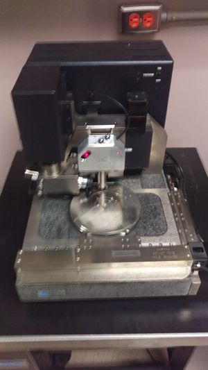
The Veeco Dimension 3000 atomic force microscope (AFM-shown on the right) is used to analyze a variety of sample sizes and types. It can function in air or liquid, making it useful for biological studies. The sample is placed on a stage which moves in the x, y, and z directions via piezoelectric elements. A cantilever with a microscopic tip moves like a spring over the surface of the sample. A laser beam reflected off the end of the cantilever is recorded on photodiodes, producing an image of the surface topography. Cantilevers vary in size from 3-100 µm with tip radii of 10-30 nm. The size of the tip and flexibility of the cantilever contribute to the high resolution of the image, which can reach 10 pm. The operating modes of the AFM (contact, non-contact, and tapping) and lateral force microscopy allow the user to access a variety of functions of the microscope. In addition to imaging, the AFM can measure the strength of inter-atomic forces and can sense the presence of individual surface atoms.[2]
For background reference
For specific link to the MTU AFM
Safety[edit | edit source]
It is far more likely that the user will damage the device, their samples, or the tools used than the user being hurt. Thus, it is important to be careful with the equipment and samples and cantilevers as they are delicate.
Equipment needed[edit | edit source]
- AFM
- Probe Holder
- Cantiliver
- Sample
Calibration & Tolerances[edit | edit source]
Initial Set up[edit | edit source]
- Sign into the Logbook
- Log into the computer
- Turn on the power in the following order
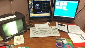
- JVC Monitor
- AFM Light
- AFM Controller Box
- Remove the dust cover from the AFM
- Start the software: Nanoscope
- Press the Real-Time icon to begin using the AFM.
- Load the correct profile by clicking on the Microscope menu
- Load a cantilever into a probe holder and attach to the AFM(be careful not to bump anything)
Alignment[edit | edit source]
- Locate the tip of the cantilever by pressing the Locate Tip icon.
- Adjust the knobs on the microscope until the end of the cantilever is in the cross-hairs on the JVC monitor.
- Hold the focus on the trackball to focus the end of the cantilever and click OK to store this position
- Use the knobs on the top of the AFM head to align the laser onto the end of the cantilever to obtain the highest sum possible(usually around 4)
- Adjust the laser spot on the photodiode using the knobs on the side of the AFM head.
- For tapping mode, the red dot on the computer screen should be centered in the cross-hairs with a vertical displacement within +-0.1V
- For contact mode, the red dot should be laterally(+-0.1V) with a vertical displacement of ~-2V
- If using tapping mode, autotune the cantilever to ensure it is a viable cantilever for use(the generated chart should be compared)
- Go back to Image Mode and check to make sure the RMS(Root Mean Square) value is between 1.9 and 2.1
Operation & Procedure[edit | edit source]
Operation[edit | edit source]
- Select the Focus Surface Icon and hold focus to move the AFM head up/down.
- Use the trackball to move the stage in the x-y plane(hold lock for large distances).
- You may need to unload the stage to allow more room to load the sample.
- Load a sample onto the stage.
- Lower the AFM head carefully at first with large adjustments but switch to delicate adjustments as the head approaches the sample. Watch both the cantilever on the JVC monitor(for the image to being to focus) and the AFM head itself to prevent crashing.
- Move to a clean area on the sample you would like to image. For reflective or transparent samples focus on the edge of the sample and then move inward to prevent crashing of the cantilever.
- Adjust the scan parameters, these will largely depend on the needed quality of data
- Scan Size: 1-10microns
- Scan rate:0.555-1Hz
- Samples/Line(resolution):256 or 512
- Slow Scan Axis: Enabled
- Adjust channels 1-3 as needed(Height and Amplitude for channels 1 and 2 are generally all that is needed)
Engaging and Acquiring Images[edit | edit source]
- Engage the tip via the engage tip icon, this will lower the cantilever tip until it comes into contact with the sample.
- Select Stepmotor from the Motor menu(Adjusting this stepmotor value will affect how much the cantilever is extended or retracted)
- It is imperative that the tip up or tip down adjustments are done slowly and carefully, as too much extension will damage the cantilever and too much retraction will prevent data gathering.
- Press tip up to retract, and tip down to extend with a goal of reaching as close to 0V as possible.
- Click the Scope Trace icon and adjust the feedback controls
- Set amplitude set point(1.1V works well for me) to a value which causes the graphs generated in scope trace to just where contact is made(if there is no contact the graphs will appear as horizontal lines).
- The lower this value is, the harder the cantilever is tapped.
- Change the data scales on the channels in order to see the graphs effectively
- When correct the graphs should match, but be offset.
- Set the integral gain(0.10 works well for me) to optimize the smoothness of the image.
- Set the proportional gain to 1.5x the integral gain.
- Set amplitude set point(1.1V works well for me) to a value which causes the graphs generated in scope trace to just where contact is made(if there is no contact the graphs will appear as horizontal lines).
- After the image parameters have been set, click the down arrow icon to being scanning again but from the top of the image.
- Click the Capture menu and select Capture Filename, type the desired filename and accept.
- Click Capture menu and select Capture Withdraw, this causes the cantilever to stop scanning after an image is completed.
- After scanning has stopped, if necessary move to another location on the sample and repeat this process starting with clicking the down arrow icon.
Modifying Images[edit | edit source]
- Click the Offline icon to view and modify captured images
- Select your image from the list
- Click Image menu and select either the right or left image, select Modify, select Flatten, select Execute, then save the image.
- Erase scanlines when they are present, they average the line above and below which may alter data significantly if many exist.
- Select any of the image types, for general analysis exporting the roughtness, section analysis, surface plot, and overall(both channels) is ideal for data gathering.
- Click the Utility menu for exporting options
- Reverse the background to obtain a white background for exporting images(ideal for publishing). Ensure that you save in the E drive folder(your name should be the folder name)
Shutdown[edit | edit source]
- If necessary withdraw the cantilever
- Click the Focus Surface icon and raise the AFM head to max position to provide ease of access to the sample.
- If needed unload the sample to provide more room to work.
- Remove the sample.
- Exit the nanoscope software.
- Turn off the AFM control box
- Turn off the JVC monitor
- Turn off the AFM light
- Replace dust cover over AFM for protection
- sign out of logbook.
Tricks[edit | edit source]
Often thin film materials, or materials which are transparent are samples measured by the AFM. This method to measure these materials only works when the sample is deposited over a transparent substrate such as a glass slide.
Orientate the glass slide so that the area of the sample to be measured is suspended into open space with the remaining portion anchored onto the AFM substrate. This removes the optical interference the glass slide introduces into the image on the TV monitor. The end result is that the edge of a very thin layer(<20nm) may be observed so that accurate positioning of the AFM cantilever may be done.
References[edit | edit source]

