- 1000 to 3000 Capacity Brick Kiln
- A Bibliography for the Solar Home Builder
- A Chinese Biogas Manual
- A Cooking Place for Large-Sized Pots
- A Design Manual for Water Wheels
- A Manual of Building Construction
- A Method for Cutting Bottles Light Bulbs and Fluorescent Tubes
- A Series of Articles on the Use of Bamboo in Building Construction
- A Sitting Handbook for Small Wind Energy Conversion Systems
- A Solar Water Heater Workshop Manual
- A State of the Art Survey of Solar Powered Irrigation Pumps Solar Cookers and Woodburning Stoves
- A Survey of the possible Use of Windpower in Thailand and the Philippines
- A Woodstove Compendium
- Adobe as a Socially Appropriate Technology for the Southwest (Solar-Adobe Sundwellings)
- Adventures with a Hand Lens
- Alternative Limbmaking
- An Attached Solar Greenhouse
- Anaesthesia at the District Hospital
- AntiPollution Lab
- Artificial Salmon Spawning
- Aspects of Irrigation with Windmills
- Basic Principles of Passive Solar Design
- Better Freshwater Fish Farming: The Fish
- Better Freshwater Fish Farming: The Pond
- Biogas Handbook
- Biogas Plants in Animal Husbandry
- Biogas Systems in India
- Biogas Technology in the Third World
- Biogas and Waste Recycling
- Bread Box Water Heater Plans
- Brickmaking in Developing Countries
- Bridging the Gap
- Brief Notes on the Design and Construction of Wood-burning Cook-stoves
- Building with Earth
- Burning Issues
- Charcoal Making for Small Scale Enterprises
- Charcoal Production Using a Transportable Metal Kiln
- Comparing Simple Charcoal Production Technologies for the Caribbean
- Comparison of Alternative Design Wheelbarrows for Haulage in Civil Construction Tasks
- Comparison of Improved Stoves
- Compost Fertilizer and Biogas Production from Human and Farm Wastes in the People's Republic of China
- Considerations for the Use of Wind Power for Borehole Pumping
- Construction Manual for PU350 and PU500 Windmills
- Construction Manual for a Cretan Windmill
- Construction Reference Manual
- Construction and Use of Simple Physics Apparatus
- Construction of Trail Suspended Bridges in Nepal
- Cook-stove Construction by the TerraCETA Method
- Cost Reduction Considerations in Small Hydropower Equipment
- Demystifying Evaluation
- Dermatological Preparations for the Tropics
- Design for a PedalDriven Power Unit for Transport and Machine Uses in Developing Countries
- Design of CrossFlow Turbine BYS-T3
- T1
- Design of Small Water Storage and Erosion Control Dams
- Design of Small Water Turbines for Farms and Small Communities
- Designing a Test Procedure for Domestic Wood-burning Stoves
- Development and Production of School Science Equipment
- Directory of Manufacturers of Small Hydropower Equipment
- Disabled Village Children
- Doing Things Together
- Double Drum Sawdust Stove
- Electric Power from the Wind
- Elementary Guide to Fish Culture in Nepal
- Elements of Solar Architecture for Tropical Regions
- Energy for Rural Development
- Energy for Rural Development (Supplement)
- Energy from the Wind
- Energy: The Solar Prospect
- Establishing a Refugee Camp Laboratory
- Evaluation of Solar Cookers
- Farm Structures in Tropical Climates
- Fish Catching Methods of the World
- Fish Culture in Central East Africa
- Fishing with Bottom Gillnets
- Food from Windmills
- Food or Fuel
- Foot Power
- Forestry
- A Forest Tree Seed Directory
- A Pocket Directory of Trees and Seeds in Kenya
- Agroforestry Species: A Crop Sheets Manual
- An Overview of Possible Uses of Sawdust
- Barnacle Parp's Chain Saw Guide
- China: Forestry Support for Agriculture
- Constructing and Operating a Small Solar Heated Lumber Dryer
- Crosscut Saw Manual
- Environmentally Sound SmallScale Forestry Projects
- Firewood Crops
- Forest Farming
- Forestry Case Studies
- Forestry for Local Community Development
- Frame Saw Manual
- Land Clearance
- Leucaena
- Make Your Own Precision Milled Lumber from Logs and Trees: Alaskan MKII
- Manual of Reforestation and Erosion Control for the Philippines
- Natural Durability and Preservation of One Hundred Tropical African Woods
- People and Trees
- Planning for Agroforestry
- Practical Guide to Dryland Farming: Planting Tree Crops
- Reforestation in Arid Lands
- Savanna Afforestation in Africa
- Short Rotation Forestry
- Small and Medium Sawmills in Developing Countries
- The Chainsaw and the Lumbermaker
- The Propagation of Tropical Fruit Trees
- Timber Drying Manual
- Tree Crops
- Tree Planting in Africa South of the Sahara
- Freshwater Fish Farming-How to
- Freshwater Fish Pond Culture and Management
- Freshwater Fisheries and Aquaculture in China
- From Lorena to a Mountain of Fire
- From the Field
- Fuel Alcohol Production
- Fuel Gas from Cow Dung
- Fuel from Farms
- Gaviotas tropical windmill
- Gemini Synchronous Inverter Systems
- General Surgery at the District Hospital
- Guidebook to Constructing Inexpensive Science Teaching Equipment
- Guidelines on Evaluating the Fuel Consumption of Improved Cookstoves
- Harnessing Water Power for Home Energy
- Helping People in Poor Countries Develop FuelSaving Cookstoves
- Hints on the Development of Small WaterPower
- Homegrown Sundwellings
- Homemade 6Volt WindElectric Plants
- Horizontal Axis Fast Running Wind Turbines for Developing Countries
- Hot Water (Morgan, Morgan, Taylor and Taylor)
- How to Build a "Cretan Sail" Windpump for Use in LowSpeed Wind Conditions
- How to Build a House Using Self-Help Housing Techniques
- How to Build an Oil Barrel Stove
- How to Construct a Cheap Wind Machine for Pumping Water
- How to Look After a Refrigerator
- How to Make Tools
- Hydro-power
- Improved Wood Waste and Charcoal Burning Stoves
- Independence Through Mobility
- Independent Energy
- Industrial Archaeology of Watermills and Waterpower
- Lab Tests of Fired Clay Stoves the Economics of Improved Stoves and Steady State Heat Loss from Massive Stoves
- Laboratory and Field Testing of Monolithic Mud Stoves
- Less Smoky Rooms
- Local Experience with MicroHydro Technology
- Local Self-Reliance
- Lorena Owner-Built Stoves
- Low Cost Development of Small Water Power Sites
- Low Cost Passive Solar Greenhouses
- Low Cost Physiotherapy Aids
- Low Cost Science Teaching Equipment
- Low Cost Wind Speed Indicator. Brace Research Institute
- Low Cost Windmill for Developing Nations
- Making Aquatic Weeds Useful
- Manege: Animal-Driven Power Gear
- Manual for the Design of a Simple Mechanical Water-Hydraulic Speed Governor
- Manual of Rural Wood Preservation
- Manual para la Construccion de la CETARam
- Matching of Wind Rotors to Low Power Electrical Generators
- Micro - Hydropower Schemes in Pakistan
- Micro Hydro electric power
- Micro Pelton Turbines
- MicroHydro Power: Reviewing an Old Concept
- MicroHydro: Civil Engineering Aspects
- MicroHydropower Sourcebook
- Microhydropower Handbook Volume 233
- Mill Drawings
- Mini Hydro Power Stations
- Model Boilers and Boilermaking
- Model Stationary and Marine Steam Engines
- Modern Stoves for All
- More With Less
- Mud Brick Roofs
- Mud Mud
- Multi-Purpose Power Unit with Horizontal Water Turbine: Basic Information
- MultiPurpose Power Unit with Horizontal Water Turbine: Operation and Maintenance Manual
- Nepal: Private Sector Approach to Implementing MicroHydropower Schemes
- New Himalayan Water Wheel
- New Nepali Cooking Stoves
- New UNESCO Source Book for Science Teaching
- Nuevas Tecnicas de Construccion con Bambu
- On Watermills in Central Crete
- One Pot Two Pot...Jackpot
- Optimization and Characteristics of a Sailwing Windmill Rotor
- Overshot and Current Water Wheels
- Painting Inside and Out
- Pair Trawling with Small Boats
- Part I
- Part II
- Participatory Monitoring and Evaluation
- Pedal Power: In Work Leisure and Transportation
- Pelton Micro-Hydro Prototype Design
- Performance Test of a Savonius Rotor
- Personal Transport for Disabled People
- Perspectives on Non formal Adult Learning
- Philippine Medicinal Plants in Common Use
- Piston Water Pump
- Plastic Sheeting for Emergency Shelter and Other Purposes
- Pole Buildings in Papua New Guinea
- Popular Manual for Wooden House Construction
- Practical Shellfish Farming
- Preserving Food by Drying
- Proceedings of the Conference on Energy-Conserving, Solar-Heated Greenhouses
- Proceedings of the Meeting of the Expert Working Group on the Use of Solar and Wind Energy
- Profitable Cage Culture
- Raising Fresh Fish in Your Home Waters
- Rattan and Bamboo
- Rays of Hope
- Reaching Up, Reaching Out: A Guide to Organizing Local Solar Events
- Reference Material for Health Auxiliaries and Their Teachers
- Renewable Energy Research in India
- Renewable Energy Resources and Rural Applications in the Developing World
- Renewable Sources of Energy-Biogas
- Renewable Sources of Energy: Biogas
- Report on Training of District Extensionists
- Report on the Design and Operation of a Full-Scale Anaerobic Dairy Manure Digester
- Rice Husk Ash Cement
- Rice Husk Conversion to Energy
- Rice Husks as a Fuel
- Roof Constructions for Housing in Developing Countries
- Roofing in Developing Countries
- Rotor Design for Horizontal Axis Windmills
- Running a Biogas Programme
- Rural Building: Basic Knowledge
- Rural Building: Construction
- Rural Building: Drawing Book
- Rural Building: Reference Book
- Sahores Windmill Pump
- Savonius Rotor Construction: Vertical Axis Wind Machines from Oil Drums
- Sawdust Burning Space-Heater Stove
- Selecting Water-Pumping Windmills
- Selection of Materials for Burnt Clay Brick Manufacture
- Self-Help Construction of 1-Story Buildings
- Self-Help Practices in Housing
- Set of Construction Drawings for PU350 and PU500 Windmills
- Shaft Lime Kiln
- Shelter
- Shelter II
- Simple Bridge Structures
- Simple Dental Care for Rural Hospitals
- Simplified Wind Power Systems for Experimenters
- Small Earth Dams
- Small Hydroelectric Powerplants
- Small Hydropower for Asian Rural Development
- Small Michell (Banki) Turbine: A Construction Manual
- Small Scale Brickmaking
- Small Scale Hydropower Technologies
- Small Scale Lime Burning
- Small Scale Manufacture of Burned Building Brick
- Small Scale Renewable Energy Resources and Locally Feasible Technology in Nepal
- Small-Scale Production of Cementitious Materials
- Soil Block Presses
- Soil Cement
- Soil cement
- Solar Dwelling Design Concepts
- Solar Photovoltaic Products - A Guide for Development Workers
- Solar Powered Electricity
- Solar Water Heaters in Nepal
- Splitting Firewood
- Standard Trail Suspended and Suspension Bridges
- Steam Power
- Syllabus for Irrigation with Windmills
- Technical Report dealing with the TOOL Windmill Projects 1977-1981
- Technology Markets and People: The use and misuse of fuel stoves
- Technology for Solar Energy Utilization
- Testing Timber for Moisture Content
- Testing the Efficiency of Wood-Burning Cookstoves
- Thatching
- The Anaerobic Digestion of Livestock Wastes to Produce Methane
- The Banki Water Turbine
- The Biogas-Biofertilizer Business Handbook
- The Complete Book of Heating with Wood
- The Construction Installation and Operation of an Improved Pit-Kiln for Charcoal Production
- The Construction of a Transportable Charcoal Kiln
- The Dhading MicroHydropower Plant: 30kWe
- The Economics of Renewable Energy Systems for Developing Countries
- The Food and Heat Producing Solar Greenhouse
- The Fuel Savers - A Kit of Solar Ideas for Existing Homes
- The Gaudgaon Village Sailwing Windmill
- The Haybox
- The Heat Generator
- The Homebuilt WindGenerated Electricity Handbook
- The Homemade Windmills of Nebraska
- The Kenya Ceramic Jiko
- The New Solar Home Book
- The Owner Builder's Guide to Stone Masonry
- The Owner Built Home
- The Owner Built Homestead
- The Passive Solar Energy Book
- The Planning Installation and Maintenance of Low-Voltage Rural Electrification Systems and Subsystems
- The Power Guide
- The Principles and Practices of Primary Health Care
- The Production of School Science Equipment
- The Provision of Spectacles at Low Cost
- The Segner Turbine: A low-cost Solution for Harnessing Water Power on a very Small Scale
- The SocioEconomic Context of Fuelwood Use in Small Communities
- The Solar Cookery Book
- The Solar Energy Timetable
- The Solar Greenhouse Book
- The Solar Survey
- The Timber Framing Book
- The Tooth Trip
- The Use of Bamboo and Reeds in Building Construction
- The Use of Pedal Power for Agriculture and Transport in Developing Countries
- The Use of Wheelbarrows in Civil Construction
- The Village Health Worker
- The Wind Power Book
- The Yurt
- Towards Scientific Literacy
- Traditional Bridges of Papua New Guinea
- Traditional Suspension Bridges in Taplejung District
- Trees as an Indicator of Wind Power Potential
- Tropical Oysters
- Vegetation as an Indicator of High Wind Velocity
- Vertical Axis Sail Windmill Plans
- Water Power for the Farm
- Watermills with Horizontal Wheels
- When You Build a House
- Where There Is No Dentist
- Where There Is No Doctor
- Wind Power for Farms, Homes and Small Industry
- Window Box Solar Collector Design
- Windpower in Eastern Crete
- Windpumping: A Handbook: World Bank Technical Paper Number 101
- Windpumps for Irrigation
- Wood Conserving Cook Stoves Bibliography
- Wood Conserving Cook Stoves: A Design Guide
- Wood Frame House Construction
- Wood Stoves: How to Make and Use Them
- Wooden Bridges
- Young Mill-Wright and Miller's Guide
- Your Own Water Power Plant
| Type | Water pump |
|---|---|
| Location | Quebec, Canada |
| Status | Designed |
| OKH Manifest | Download |
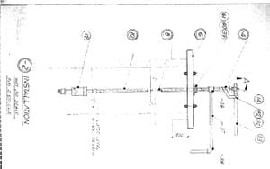
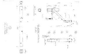
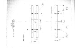
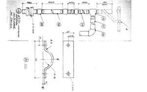
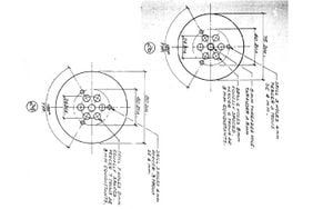
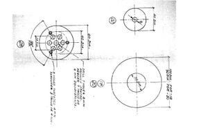
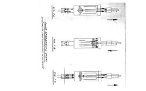
This document gives schematic drawings of the assembly and operation of a wind powered water pump. The drawings are accompanied by a list of parts and materials used in the pumps manufacturing.
Contents
Publisher[edit | edit source]
Brace Research Institute
MacDonald College
McGill University
Ste. Anne de Bellevue 800
Quebec, Canada
H9X 1CO
1977
Publication Number T-114 Go back to AT Sourcebook
Installation[edit | edit source]

Assembly[edit | edit source]
Piston and Piston Rod[edit | edit source]
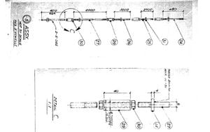
Washers and Piston Head[edit | edit source]
Operation[edit | edit source]
Parts and Materials[edit | edit source]
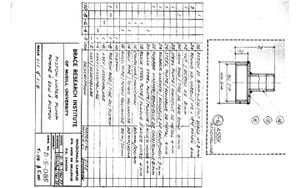
List of Parts and Materials[edit | edit source]
- 36 - Nut Bored at 8mm
- 34 - Round HD-Screw 4mm
- 32 - Nut 8mm
- 30 - Iron Rod 8mm
- 28 - Steel Plate 4mm
- 26 - Steel Plate 4mm
- 24 - Rubber Washer 5mm
- 22 - Rubber Washer 5mm
- 20 - Black Steel Plate 4mm
- 18 - Black Steel Plate 4mm
- 16 - Coupling 90mm/100mm
- 14 - Galv. Pipe 33mm/42mm
- 12 - Galv. Pipe 80mm/90mm
| Keywords | water pump, water, energy, renewable energy, appropriate technology, wind power, water supply, pumping |
|---|---|
| SDG | SDG07 Affordable and clean energy |
| Authors | Jessica Larmer |
| License | CC-BY-SA-3.0 |
| Language | English (en) |
| Related | 0 subpages, 342 pages link here |
| Aliases | Piston Water Pump, AT Sourcebook/Piston Water Pump |
| Impact | 6 page views (more) |
| Created | January 26, 2010 by Dan |
| Last modified | June 18, 2024 by Felipe Schenone |
| Cite as | Jessica Larmer (2010–2024). "Appropriate Technology Sourcebook/Piston Water Pump". Appropedia. Retrieved September 20, 2024. |
| API queries | basic, semantic, html, files, more |
Retrieved from "https://www.appropedia.org/w/index.php?title=Appropriate_Technology_Sourcebook/Piston_Water_Pump&oldid=1111315"
Cookies help us deliver our services. By using our services, you agree to our use of cookies.