
StartUp Humboldt lectern

| Type | |
|---|---|
| Authors | Lonny Grafman Emilio Mark Burg Kolby Nixon Zeke Lopez Erika Ospenson |
| Status | Deployed |
| Years | |
| Made | Yes |
| Replicated | No |
| Uses | education, science |
| Map | |
|---|---|
| Location | Arcata, United States |
| Coordinates |
We are the team "Sit Down, Be Humboldt" and we were tasked for creating a lectern for the StartUp Humboldt space which is occupied by the Small Business Development Center, to aid in presentations and public speaking. This product was designed over the course of the Fall 2025 Semester at Cal Poly Humboldt, overall taking approximately 15 weeks of development. We were budgeted $200 for the overall creation of the lectern for materials. The intended users of the lectern are presenters and public speakers within the StartUp Humboldt space. Our team was motivated to solve their lack of a lectern, due to the aid it would have in presentations and the hope that would help in the financial prosperity of the area through local small businesses.
Background
[edit | edit source]Our team chose to attempt to create a lectern for the StartUp Humboldt space which is occupied by the Small Business Development Center in down town Arcata, to aid in presentations considering they did not have an aid prior. Immediately in choosing this project we were given the email address for Samantha (Our stakeholder) to coordinate repeated meeting times for updates and feedback. At the start of the Fall 2025 semester we began brainstorming ideas periodically and going to the meetings for advice on what to improve, cyclically improving the final design according to their needs.
Problem statement
[edit | edit source]The objective of this project is to create a lectern for the StartUp Humboldt space to be used to aid in presentations and public speaking. In using this infrastructure in presentations, presenters will have a space for presentation accommodations such as their laptop, paper storage, a battery pack for their laptop, a microphone holder, caster wheels for easy mobility, and a storage space for the user's water bottle. This lectern would allow the presenters to be more prepared for presenting relevant information regularly to audiences, allowing a presence for the presenter to be the focal point of the room.
Criteria
[edit | edit source]Based upon the necessary requirements for this project, our team divided it into what we believed were the most important using a Delphi table to adequately define them. Since we were assigned a fixed budget and found it necessary to not over spend, we allocated cost at a weight of 5. The stakeholder was very clear about the need for this lectern to be durable and able to be used for a long period of time, making it have the highest weight of importance. Aesthetics are equally important to have the lectern be an accepted piece of infrastructure within the space, and ultimately not be an eye sore. Lastly, since we had a fixed amount of time to work on the lectern, our team put an importance weight of seven, to illustrate the importance of delivering the lectern on time.
| Criteria | Description | Weight (1-10) |
|---|---|---|
| Cost | Material costs associated with the construction of the podium, and barring hours spent from students' involvement creating it. | 5 |
| Durability | The ability for the podium to withstand years of consistent use with appropriate maintenance. | 8 |
| Aesthetics | The stakeholders acceptance and relation to the design elements which can be quantified through acceptance scores. | 8 |
| Time | The project needed to be completed in the standard semester time window. | 7 |

Prototyping
[edit | edit source]The initial design of the lectern was a basic rectangular prism with a flat top surface to allow for a presenter to place a laptop, tablet, or other devises atop. The lectern was meant to be an absolute base that met all of the criteria and needs of the client. While it does meet all the needs of the client, it lacks aesthetics.
.jpg)
The next designs incorporated a tapered, angular design as the client indicated they wanted something a little more modern looking. After researching aesthetic properties of a modern lectern, this design incorporated compound angles and a sleek, simplistic modern look. A secondary lectern of the same design was created with a podium/stand to increase the height of the lectern if desired.
.jpg)
.jpg)
While the client was interested by the different geometry of the tapered lectern, they found it to be too official. As such, a new idea for the lectern was incorporated: different-sided polygons. "Sit Down, Be Humboldt" discussed a few options, and ultimately decided that a hexagonal prism would work the best, resulting in the following design:
.jpg)
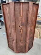
While this hexagonal prism design again met all of the criteria, all involved in the project agreed that this design looked too much like a baseball home plate. A few sketches and ideas were drawn up amongst the group, until a general unified idea was found and led to the final design of the lectern's form:
.jpg)
Final product
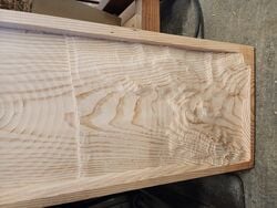
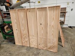
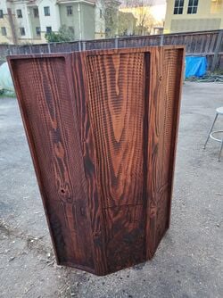
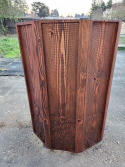
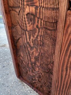
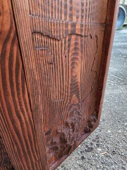
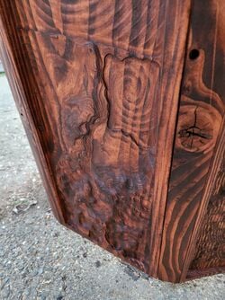
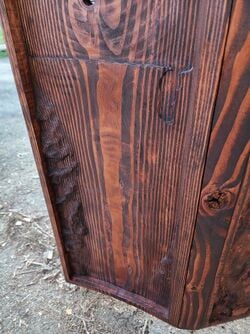
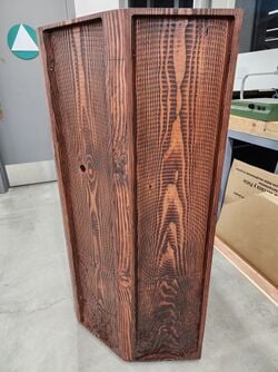
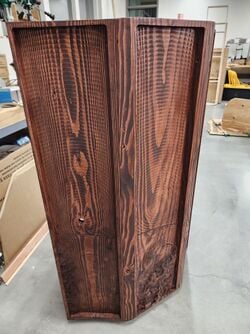
[edit | edit source]The final product is a 26" (Width) x 20" (Length) x 48" (Height) lectern. The front five panels are Douglas Fir originating as 11" (Width) x 1-1/2" (Thick) x 48" (Length) sections that are cnc-ed out to be the topographical map of the local area. The interior of the lectern is fortified by 1-1/2" (Width) x 3/4" (Thick) to form a durable frame. Next, 1/4" thick prefinished birch plywood to form shelves for storing presentation materials. Lastly we stained the topographical map to accentuate the land features so as to not distract from the presenter.
[Describe your final product here with image and labels. Start with the biggest overview first.]
Design and Construction
[edit | edit source]
The first step in creating a topographic map cutout (whether you want to create a stylish lectern, a sample for a client, or a cool piece of art) is to obtain a DEM (digital elevation model) of the region you would like. We chose to create a lectern with a topographic relief of a specified region of Humboldt County utilizing the website: map2stl.com. While this site is intended to create .stl files for 3D printing, we knew these file types could be converted into mesh files to be used in Fusion 360 for design and CNC (computer numerical control) operations programming for the final product. This site allows any user to pick and choose their desired geographic region, size of the DEM they want, and other parameters for topographic maps.

Once you have chosen your desired region, download the map .stl file. Then, upload that .stl file into Fusion 360. With the .stl topographic map uploaded, now create the form you would like to create. For our purposes, we were creating a hexagonal prism lectern, so five identical panels measuring 11x48x1.5” were created as the bounding boxes for CNC operations and laid over the map, then scaled the mesh under the MESH tab of Fusion 360, and using the “MODIFY” -> “Scale Mesh” to an appropriate scale. You may have to play with the scaling for a bit until you find a scale that meets your requirements.
With the geographic are you want within your specified, you can now trim the map down to size using the “PLANE CUT” function under “MODIFY” within the MESH tab. Select your mesh (the .stl topographic map uploaded), then select one of the inside edges of your bounding box for the “Cut Plane” and select “Ok”.

Every time you cut the mesh, ensure to repair the mesh by selecting the “Hazard” warning sign next to the mesh under the “Bodies” tab under the browser on the left-hand side of the screen.
Select the mesh again, and choose your Repair Type. For our project, the repair type used was “Stitch and Remove”, which did not cause any adverse issues to the final product. You must repair the mesh every time it is cut. Refraining from repairing the mesh after every cut operation may result in a mesh geometry that is no longer readable by Fusion 360 and it will not register within the Manufacture tab for CNC programming. Repeat this process for every edge of your bounding box (ensuring to repair the mesh after it is cut each time).
With the map cut into its frame, the z-height must be adjusted so it properly fits within your bounding box and can be properly milled via CNC. Once again, select the mesh, then “MODIFY” -> “SCALE MESH” under the MESH tab. For this operation, only the Z-Scale will want to be changed, so select “Scale Type” -> “Non Uniform”, then adjust the Z-Scale. Again, you may have to play with the Z-Scale for a bit to achieve your desired height. Scaling the Z-Scale too high (a factor of 4) will result in very exaggerated topographic features, and scaling the Z-Scale too low (a factor of 0.5) will result in indistinguishable topographic features (i.e. hills/mountains become too flat, water features disappear into coastline/ocean, etc.)
Ultimately, our Z-Scale was reduced to 0.7 to fit within our bounding box. The design of the lectern incorporated five identical 11x48x1.5” wooden panels, and each panel would have 10x47x1” volume of material effectively removed via CNC milling, so there was 1” allowance for topographic and ocean features.
Cut the top layer plane to ensure all features shown are within your bounding box by using the Plane Cut function, then repair the mesh.

If you are creating a triptych piece similar to our design; use the sketch function under the SOLID tab to create lines in between each post of your bounding box to match your final desired dimensions. Then, use the Split Body function within the SOLID tab to split your frame into individual pieces.
If you intend to do further design work, it is recommended that you separate the mesh and the matching boundary. Select the mesh and its adjoining bounding box and separate them.
The final lectern design for our project is a hexagonal prism, with five equal faces measuring 11x48x1.5” to create the body of the lectern, with an open back for storage purposes. To create the shape and form requested, 135° angles would need to be created between each panel. This was achieve by creating 45° angle cuts in each of the side and corner pieces on their inner-facing sides.
45° angle triangles were drawn onto the solid frames on the inner bottom sides of the side and corner, then negatively extruded -48” to “remove” material that will be physically removed in the future. Completing the extrusion will expose the mesh, and will need to be Plane Cut so that the CNC will create the proper angles for the final form. Under the MESH tab, select Plane Cut, select the mesh within the proper boundary, then use the newly “cut” 45° angle as the Cut Plane. Repair the mesh, and continue the process for every 45° angle.
With the exterior of the frame and mesh cut, the interior needs to have the same 45° angle cut into it. Sketch a 45° angle line from the top of the frame to the bottom of the frame. Double check that the angle does match the exterior angle. The interior of our lectern frame was off and we had to adjust during the fabrication/construction phase to account for this.
Select your sketched polygon, and extrude it the length of your frame interior. Now, cut your mesh again using the Plane Cut function within the MESH tab, and use the new interior angle as the Cut Plane, and as always, repair the mesh!

The mesh has now been split into individual pieces, but the mesh along every interior wall of frame(s) will need to be split. If you have a five frame design, you will need to use the Plane Cut function multiple times, with mesh repairs in between each Plane Cut.
With the mesh cut into separate pieces, the mesh and solid frame must be combined into one body/object. This can be achieved by turning the mesh into a solid, or the solid into a mesh. The former did not work for this project, so the latter was employed. To convert a solid into a mesh, select your solid frame, then under the MESH tab, select “CREATE” -> “TESSELATE” -> “OK”.
The two meshes (or solids) must be combined into one object. Under the MESH tab, select Combine. The function is the same under the SOLID tab. Select the topographic map mesh as the Target Body, and the corresponding bounding box as the Tool Bodies. Select the Merge operation, then OK. Congratulations! The modeling/design portion is complete.
These designs can be exported as a .stl or .step file as-is for 3D printing. During our client meetings, updates to the design were printed out and presented to the client so they could see the physical form of the desired lectern.
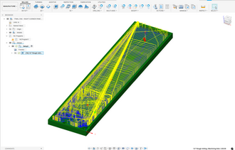
Lastly, hide each panel that is not being programmed for CNC operations, then move from the DESIGN portion of Fusion 360 to the MANUFACTURE tab. Ensure your machine setup and parameters are correct and match the capabilities of the CNC you will be operating on. As the aesthetics of our final design incorportated a topographic map, we elected to only use a ½” flat end mill to allow the topographic layer lines to be pronounced. If a smoother finish is desired, a 1/8” – ¼” ball end mill is recommended.
Two operations were the best candidates for clearing a large volume of material, while also being able to provide the details of the topographic map: Adaptive Clearing, and 3D Pocket. Adaptive Clearing was chosen as it had slightly faster operating times. As the design had nearly two-thirds of the frame being empty to represent the ocean, and the workpiece material (Douglas Fir) is a relatively soft wood, the depth of cut was increased to a maximum of 90% of the diameter of the cutting tool, or .45” to reduce operating times of the CNC. Operating times were further decreased by reducing the tolerance from .004 to .1”. The operating time to successfully mill our 10x47x1” volume of material ranged from 2:40:00 to 3:40:00. Estimates with smoothing the topographic features with a ball end mill extended operating times from 5:30:00 to 7:40:00 depending on the level of detail and complexity of the topographic features.
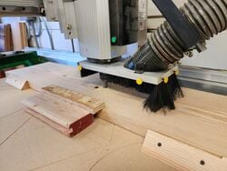
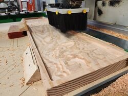
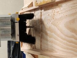
Due to the large volume of material being evacuated from the workpiece, a CNC operator must be present at all times to ensure the chips do not cause/risk fire-hazard. To prevent this, a CNC operator was present at all times the CNC was in operation with access to to compressed air to blow the chips off the workpiece. The forces undergone by the workpiece during CNC operations also required bracing along the sides and top of the workpiece. Enough downward thrust was created that the CNC ultimately pushed one of our workpieces out of place by several inches.
After CNC operations have been completed, the topographic map is ready for fabrication and construction.
- Various stages of CNC programming and operation.
-
-
-
-
-
-
-
 Various stages of CNC programming and operation.


Fabrication and Construction
The fabrication of a topographic lecturn will be highly dependant on the topographic map used; while our methods are a good jumping off point, they may not be comprehensive because each topographic lecturn will be unique.
- The CNC'd panels need to be sanded and finished to the desired grade of sandpaper, we finished sanding at around 180 grit. Flat water portions may be done quicker with an orbital but it is advised to work by hand on the topography features to preserve them.
- Cut panel length wedges with 22.5 degree angles on either side to create long trapexoid shaped pieces. The long width of the trapezoid will be the exterior face of this connecting rib, the short face the interior. These pieces will go between the panels to ensure that the vertical boarders of the CNC'd boards will not be compromised as they are joined together while ensuring they will be able to curve nicely.
- Lay the CNC'd panels out in order, then take the rib wedges and put them to the left of all of your panels but the last one. The next part is better with a friend.
- Have one person hold the panel so the shortest edge of the panel is vertical. The other person will select places to countersink and pre-drill holes for the mounting hardware. At this point the specific image of your chosen topo will come into play. Choose places at the top and bottom of your boarder to drill through, these will vary based on the topo features and what angle the drill can be held at.
- Repeat this for all the sides of the panels that will be adjacent to the rib wedges.
- When all your pre-drilled holes are complete, the panels will be attatched too their ribs in order. Attatch only one rib to each panel! This makes it much easier to assemble them all together.
- Now take the leftmost panel (with the rib on the right side) and stand it vertically on a level surface. Take the next panel in the sequence and line them up so the tops of the boards and ribs are as flush as possible. Screw in the top pre-drilled hole, then repeat at the bottom. Ensure the screws are torqued in to suck the rib into the new adjacent panel.
- Repeat this process going all the way around until all the panels are connected and making a crescent shape.
- Now take a brad nail gun, or finish nail gun, and run it along in between the screws in the top and bottom of each panel, ensuring you are nailing from the interior of the panel boarder towards the rib. Be cautious of your angle here so you don't let your nails shine through the front of your ribs, unless that's the look your're going for.
- Now take some cardboard, set it on top of the lecturn and scribe the shape for the shelving and work surface. I recommend using a jig saw for this and following the line exactly if your lecturn is irregular. Now use that as the template for your shelving. Use your cut out shelf to decide the angle of your work surface, scribe around the bottom of the work surface when it is in your desired position.
- Now measure the angles where the panels and ribs meet from the inside, take 1"x0.5"x10' lumber and cut it with that corresponding angle. These will be how we support the work and shelf surface. Cut the length of these for however wide your panels are. Secure them to the ribs/panels carefully, be mindful that you don't punch through your hard earned topography art. They should have their top edge on the scribed work surface/ shelf line.
- Now brad nail the shelves into the ribs from the top of the work surface, take your time so you don't create shiners.
- Sand the top rim of the panels/ribs so they are all nicely flush. Sand the bottom and the front facing sections of the wedge rib joints if need be.
- Perform stain tests of scrap wood, once you've chosen your desired number of coats stain the lecturn, shelves, and ribs accordingly. Perform whatever finish you've chosen, we chose a single layer of polyacrylic that we brushed on lightly.
- Pre-drill holes in the bottom of the lecturn for your wheels in their desired locations and install the wheels.
- Drill the charging port hole in the work surface and cover it with plastic port organizser (preferably 3D printed).
- Add mic stand and revel in your and your friends hard work and accomplishment.
-
-

-
-
-
-
-

-
-
-
-

-
-
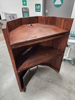 Gallery of completed lectern, designed, created, and fabricated by Sit Down, Be Humboldt.


Video instructions
[edit | edit source]Final video to be updated.
Bill of materials
[edit | edit source]Description of costs, donations, the fact that this is just proposed, etc. For a simple cost table, see Help:Table examples#Cost Table and Template:Bill of materials for two nice formats.
| Item | Amount | Cost $ |
|---|---|---|
| Douglas Fir Panels | 5 | $90.06 |
| Caster Wheels | 4 | $12.24 |
| Birch 1/4" plywood sheet | 1 | $37.50 |
| Red Oak Stain | 2 x 12 Oz Can | $14.32 |
| Total | $168.34 |
Maintenance
[edit | edit source]Due to the mainly stationary aspect of the lectern, maintenance has a large period of time especially when the materials are respected. Due to the wooden nature of the lectern, the main maintenance is sealing the wood to reduce the effects of water and high humidity from the region which is dependent on the wood. With the battery bank to charge a laptop, the battery bank must be charged prior if intended to be used. Lastly, for the occasional movement of the lectern, wheels must be free of debris that could inhibit their movement.
[Introduce this maintenance section. Help ask the questions:
- Are there any needed actions for maintenance?
- How often?
- Who should perform maintenance?]
Maintenance schedule
[edit | edit source]- Daily
- Remove any beading water from surface
- Replace dead battery banks if presenting
- Weekly
- Keep wood clean
- Monthly
- Keep wood clean
- If wood appears matte, apply tung oil to wood surface
- Yearly
- If wood surfaces appear matte, apply tung oil to wood surface
- Clean caster wheels of debris
[This is when to maintain what. Please keep the format the same as it populates the kiosk in CCAT.]
Conclusion
[edit | edit source]Testing results
[edit | edit source]This will be updated when the final lectern is completed.
Describe the testing results.
Discussion
[edit | edit source]This will be updated when the final lectern is completed.
Discuss the testing results.
Lessons learned
[edit | edit source]This will be updated when the final lectern is completed.
Discuss lessons were learned during this project and what you would do different next time.
Next steps
[edit | edit source]This will be updated when the final lectern is completed.
Discuss any next steps for the project as it goes on into the future.
Troubleshooting
[edit | edit source]This will be updated when the final lectern is completed.
This is only how to troubleshoot basic operation. For complex issues, the solution might just say something like contact ________. It should be a table in this format:
| Problem | Suggestion |
|---|---|
| Example issue | Example solution or suggestion |
| Does not turn on | Make sure it is plugged in |
| Another issue | Etc. |
Team
[edit | edit source]Introduce team and semester in the following format:
- Fall 2025 - ENGR 205
- Lonny Grafman (Teacher)
- Heather Burns (Teacher)
- Mark Burg
- Zeke Lopez
- Kolby Nixon
- Erika Ospenson
References
[edit | edit source]
| Authors | Mark Burg, Erika Ospenson, Kolby Nixon |
|---|---|
| License | CC-BY-SA-4.0 |
| Organizations | Cal Poly Humboldt |
| Cite as | Mark Burg, Erika Ospenson, Kolby Nixon (2025–2026). "StartUp Humboldt lectern". Appropedia. Retrieved July 12, 2026. |