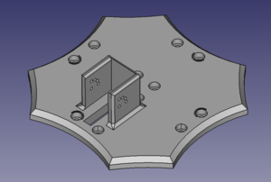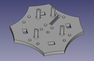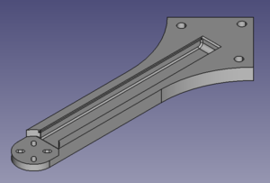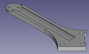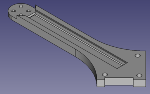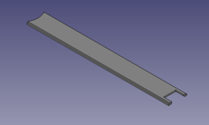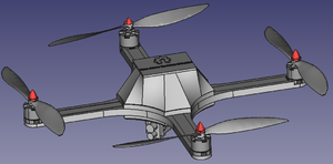
The goal of this Cinematography Quadcopter is to create an open-source platform that can be used for aerial photography and cinematography and provide a platform that can be adjusted or manipulated based on the objectives of the quadcopter.
Background[edit | edit source]
The goal of this project is to create an open-source quadcopter platform that is able to capture 4K resolution pictures and videos. This platform is based on previous open-source hardware to control the software and electronics of the quadcopter, and the frame is designed using the open-source software FreeCAD to make a 3D printed frame. This 3D printed frame and open-source components makes the cost of this project minimal while maintaining a reliable and customizable platform. The quadcopter also contains features to make it weather resistant in order to increase its longevity.
Problem Statement[edit | edit source]
The current market options for a quadcopter that supports a 4K resolution camera are limited and expensive. Using common quadcopter components and open-source options, this solution allows the common user to build off this existing platform to create the quadcopter to fit their needs. This platform allows the user to manipulate or change features on the frame while using software that is completely open source and free to the public. This eliminates the expensive costs of prototyping and allows the user to customize the quadcopter to add additional payloads.
Project Significance[edit | edit source]
This quadcopter allows the user to create a customized platform to suit their cinematography needs. It allows the user to add additional payloads or alter the dimensions of the frame to make a larger or smaller quadcopter to fit each scenario.
Project Goals:
- Create a frame platform using open-source software
- Use FreeCAD to create 3D models of the frame
- Use open-source plugins in FreeCAD to create a 3D assembly of the frame
- Use open-source plugins in FreeCAD to perform FEA analysis
- Withstand a fall while in flight
- Utilize PETG filament to 3D print the frame
- Control the quadcopter using a handheld remote control
- Utilize an Arduino Uno R3 to control the operations of the quadcopter
- Weather resistant
- Create a cover to house the essential components inside the center of the quadcopter
- Verify each components works properly on its own as well as with each other
- Create a demo of the quadcopter in flight and sample photos and videos
Future Goals:
- Create mounting for an additional payload
- The quadcopter will have an attachment on the underside to attach additional cameras or equipment
- Utilize the GoPro mounting system
- Attach a LiDAR sensor to the quadcopter
- Allows for the "Follow Me" function as well as autonomous hover
- Attach a GPS unit
- Allows for GPS location lock when paired with a LiDAR sensor for autonomous hovering
Part Choices[edit | edit source]
Because this quadcopter is open source, the components used to build the quadcopter must be accessible to everyone. Because of this, an Arduino Uno R3 was chosen as it is open source based and minimalistic. This Arduino is paired with the MultiWii drone software which allows the user to input the components chosen into the code and make adjustments. Because this software was chosen to fly the quadcopter, typical components were chosen to simplify the prototyping process. Emax MT2213-935KV motors were chosen as each motor can produce a maximum of 935kV, generating an excess of lift when paired with 10" propellers. This combination allows the quadcopter to carry an additional payload of a camera or other equipment without suffering from a lack of power. Because these high power motors were chosen, 30A BLHeli-S Rev16 V3 ESCs and a 3S lip battery were also chosen to power the motors. These components ensure that the motors are provided with plenty of power while being able to fly for an extended period of time. In order for the quadcopter to accurately determine its pitch, yaw, and roll, a GY85 9 degree of freedom IMU was implemented. Each of these components allows the quadcopter to fly safely and effectively. After these components were chosen, a camera must be chosen to deliver the 4k photos and videos. The camera that was chosen for this task was the RunCam Hybrid Micro FPV camera. This camera uses an onboard microSD card to capture the photos and videos eliminating the use of an external module.
Filament Choice[edit | edit source]
Since this quadcopter contains powerful motors, the frame must be able to withstand not only the forces of the motors, but also the force generated from a fall or crash. Because of this, PETG was the chosen material for the quadcopter to be made of due to its impressive material properties. The frame components were 3D printed using a Lulzbot Taz Pro using a nozzle that accepts 2.85mm filament.
Printing Settings[edit | edit source]
In order for the frame to be strong enough to survive a fall, a high infill density is used. An infill density of 80% with an infill pattern of triangles was used. This infill pattern and density allows the frame to be strong enough to survive a fall but reduces the weight when compared to 100% infill pattern. The high detail setting was also used with a layer height of 0.18mm.
Frame Components[edit | edit source]
| Part | Description | Count |
|---|---|---|
| Bottom Plate with mount for the RunCam Hybrid Micro FPV Camera. | 1 | |
| Top plate with mounts for Arduino Uno R3. | 1 | |
| Rear arms. | 2 | |
| Front Left Arm. | 1 | |
| Front Right Arm. | 1 | |
| Sliding covers for the arms. | 4 | |
| Center cover to protect the essential electronics. | 1 |
Fall 2021 Senior Design Paper[edit | edit source]
Executive Summary[edit | edit source]
The Open Source Hardware Enterprise is a team of engineers, working to expand the open-source community by providing and building upon new or existing platforms. These platforms are entirely community built, tested, and driven, allowing any user to recreate the project or tailor it to their own needs. An open-source quadcopter was developed by the Open Source Hardware team to allow hobbyists and researchers to attach various equipment to it to capture any kind of data. To do this, the quadcopter was created utilizing open-source software, tools, and hardware to create a platform that can be used and modified by anyone. To show the expandability of the quadcopter, a 4K First Person View (FPV) camera, the RunCam Hybrid Micro, is being used as a payload to demonstrate its capabilities as a cinematography quadcopter.
The frame of the quadcopter was designed with a large, flat surface area on the bottom, combined with a high-resolution camera allowing the user to capture high quality photos and videos while attaching additional equipment, sensors, and payloads for various tasks. The design of the quadcopter combined with the components and materials chosen, allows it to be easily modified, while retaining its strength during flight and impact. A 3D computer aided design (CAD) model was created using FreeCAD, an open-source CAD software. This software allowed the team to create the frame and test it using Finite Element Analysis (FEA) to ensure it was able to withstand the load of the quadcopter under operation. The FEA results yielded low stress and displacement values under maximum thrust and impact, with various components designed to fail under impact loads to reduce the damage to the main frame components. This frame design was then manufactured using 3D printing technology, using Polyethylene terephthalate glycol (PETG) to retain its strength, while reducing the weight of the frame, allowing for addition payloads to be carried. To carry the payload, the Emax MT2213-935KV motors will be used, combined with 10" propellers. This motor and propeller combination allows the quadcopter to carry heavy payloads and be agile during flight.
The open-source software, MultiWii, is used to control the quadcopter, giving the user the ability to modify every part of the code. Because MultiWii is an open-source project, its features and accessibility are constantly expanding with a large support base from the community, making it an excellent choice as a flight controller. This software runs off an Arduino microcontroller, making every portion of the quadcopter open source besides the standard essential quadcopter components. Utilizing open-source flight controller software allows implementation of devices normally not found on quadcopters, allowing its use by researchers to gather sensitive data from a remote location. MultiWii offers an extensive library of features and an enhanced GUI allowing testing to be done prior to initial flight to ensure that each component will work properly. Preliminary testing of both the motors inputs and responses as well as the Internal Measuring Unit (IMU) were done through the MultiWii GUI prior to connecting the components to a power source to test the balance, responsiveness, syncing of the quadcopter during flight.
Acknowledgements[edit | edit source]
The cinematography quadcopter team would like to extend its gratitude to the rest of the Open-Source Hardware Enterprise (OSHE) team for their support with this project, as without the team's input, various elements of the project would not have been reconsidered, weakening the design of the quadcopter. The team would also like to thank Dr. Shane Oberloier for assistance with understanding complex electrical circuits and Arduino coding, and Rick Berkey for his support and guidance throughout the project, offering insight as to how to improve the design. Their support and guidance allow the team to continuously improve their skills and knowledge, leading to more innovative and effective solutions. I would also like to thank Harris Neill for his help during the first semester understanding the MultiWii code, and Joaquin Ganoza for his help during the building and testing phase of the project, helping me troubleshoot various problems that arose during the project.
Introduction[edit | edit source]
The basis of a quadcopter is to allow data to be collected from an aerial point of view. This data can be anything from pictures, air density, temperatures, or other forms of data from additional sensors. The most common use of a quadcopter is for cinematography, as many users attach a camera to capture high-resolution photos and videos. Due to the design limitations of many quadcopters on the market, additional accessories are rarely added to existing quadcopters, leading users to either build a new design or buy another frame for each device. The opportunity exists for a design that can be adapted to each user's requirements by being semi-modular or having the ability to mount multiple different components to the frame with minimal complexity. Creating such a design would be to create an open-source platform for users to consistently expand and support new an innovative ideas and solutions.
Objectives and Constraints
Objectives
The goal for this project is to design and manufacture an open-source quadcopter that is designed around the expandability by any user. This means that the design should be easy to manufacture for anyone with basic open-source tools, and should be easy to operate and set up, while having the ability to be adapted to any needs the user has (additional payload, visual changes, performance changes, etc.). To do this, the goals of the project are as follows:
- Open-Source frame design
- FreeCAD will be used allowing anyone with access to a computer to make changes and use the design.
- Open-Source code controlling the quadcopter
- Open-source project (MultiWii) will be used as a foundation to control the quadcopter.
- Water-Resistant design
- 4K video capture
- Integrating a common 4K quadcopter camera to be used through the Arduino coding to capture up to 4K photos and video.
§ Photos and videos will be saved to the onboard micro-SD card inside the Arduino.
- Open-Source controller hardware.
- Eliminates the proprietary microcontroller found in every quadcopter on the market.
- Allows the community to use different styles of Arduino controllers to add functionality or reduce weight for purposes such as racing.
- 3D printed frame
- Allows changes to the frame to be printed easily and quickly reducing the manufacturing time.
- Perform basic quadcopter flight maneuvers
- Ability to be controlled from a handheld transmitter.
- Take off and land safely.
- Precise and accurate controls.
Constraints[edit | edit source]
Due to the nature of the project, many users will not have access to proprietary/specialty software and tools. This limited accessibility leads the user to seek out other means of design and operation. Other concerns such as strength and durability need to be considered as damage to the quadcopter can be dangerous to both the components, pilot and bystanders. To address these concerns, multiple limitations are placed on the project to make it accessible to everyone:
- Open-source software will be used to design and develop the frame and electronics
- FreeCAD (Open-source CAD software) will be used to design the 3D model of the frame
- MultiWii Arduino software will be used to generate the code required to fly the quadcopter
- Open-source tools will be used to manufacture the frame of the quadcopter
- 3D printing will be the basis of manufacturing for this project, as it allows almost any user to manufacture the frame of the quadcopter
- Must be able to withstand forces both during flight and during an uncontrolled landing
- Every component needs to be covered and the quadcopter needs to be water-resistant in the event of inclement conditions during flight or landing
- Reduce cost to under $550 for final product minus testing equipment.
- Complete the project within a 2-semester time frame.
- Follow FAA regulations8.
- Thrust to weight ratio of 2.
Project Planning and Timeline[edit | edit source]
The project's timeline can be found below in Table 1, where the majority of the design work was the focus during the first 14 weeks, while the remaining duration of the project was focused on the electrical, coding and testing of the quadcopter. This timeline was determined due to the large presence of Covid-19 during the initial 14 weeks of the project, while the second 14 weeks allowed the team to shift focus back to the lab to continue testing and analysis of the quadcopter. This timeline was followed with minor changes being made to the second semester, as unforeseen problems during the coding and testing phase utilized more time than initially intended.
Table 1: Cinematography quadcopter weekly project timeline.
| Week | Milestone (Spring 2021) |
| Week 1 | Begin semester / Initial contact with advisor |
| Week 2 | Draft project plan and submit approval request |
| Week 4 | Finish BOM item selection and have parts on order |
| Begin design of the quadcopter frame | |
| Week 8 | Finish design of quadcopter frame |
| Begin coding Arduino and adapting selected parts | |
| Week 9 | FEA analysis on the quadcopter frame |
| Begin printing quadcopter frame | |
| Week 10 | Test fit printed parts and make adjustments |
| Exam week | Enterprise Review |
| Week | Milestone (Fall 2021) |
| Week 1 | Begin semester |
| Week 2 | Finish code for the Arduino |
| Week 3 | Begin testing code |
| Week 4 | Make revision in code |
| Week 5 | First test flight |
| Week 6 | Achieve stable hover and control while flying |
| Week 7 | Generating video and photo from the onboard camera |
| Week 10 | Begin documentation |
| Week 14 | Final documentation and presentation |
Project Budget
The estimated cost can be seen in Table 2 below. This budget is divided into multiple different categories, as some components were used strictly for testing and were not used in the final design of the quadcopter. Because of this, the total cost for the quadcopter can be reduced by eliminating these parts. Other components that were used may or may not be available due to the rapid growth in the quadcopter community, as certain components are often replaced quickly with updated versions. An example of one of these components would be the IMU, but a replacement for this component can be easily sourced if it has the same degrees of freedom as the one that is currently being used. Many of these parts can be sourced directly from the manufacturer's website/store, while most of them were sourced from a third-party source. As seen in Table 2, the team was able to undercut the budget of $550 by $30.37 including the testing equipment (goal was to keep the budget below $550 without testing equipment).
Table 2: Cinematography quadcopter itemize project budget.
| Item | Quantity | Estimated Price | Spent |
| Components | 370 | ||
| Battery | 1 | $17.09 | |
| ESCs | 4 | $59.92 | |
| Brushless Motors | 4 | $61.36 | |
| Arduino Uno R3 | 1 | $23 | |
| 4k Camera | 1 | $90.97 | |
| 1045 Propellers | 1 package | $11.99 | |
| Flysky receiver | 1 | $17.37 | |
| FrSky Receiver and Transmitter Combo | 1 | $58.59 | |
| Arduino Uno R3 Prototype PCB | 1 package | $18.99 | |
| Hardware | $150 | ||
| M4 socket head cap screws | 1 package (12 used) | $7.81 | |
| Tapered Heat set inserts | 1 packager (12 used) | $6.58 | |
| 1N4001 Diodes | 1 | $2.03 | |
| 40 pin snap headers | 2 | $1.94 | |
| Bullet Connectors | 1 package | $7.99 | |
| 12awg Wire | 1 package | $9.36 | |
| 18awg Wire | 1 package | $6.98 | |
| PETG Filament | 2 rolls | $63.98 | |
| Testing Equipment | 30 | ||
| Battery Voltage Meter | 1 | $7.23 | |
| Power Distribution Blocks | 2 | $11.08 | |
| Power Distribution Block Jumpers | 2 | $6.04 | |
| Total | $550 | $519.63 |
Conclusions and Future Work[edit | edit source]
This cinematography quadcopter integrates open-source software and hardware to create a foundation for the open-source community to build upon. This quadcopter utilizes a 3D printed frame using PETG to achieve the desired strength, although the design can be easily printed in other materials based on the needs of the application, while being designed using the open-source CAD software FreeCAD. The use of FreeCAD allows any user to make changes to the frame by changing the design, such as adding mounting locations for additional equipment without the need for specialty software. The frame was designed to achieve the maximum rigidity in the key components such as the arms and base plates, while other components were designed to flex and break under high loads. The arms were designed with a FOS of 5.51, allowing it to withstand large impacts before yielding, while the feet of the quadcopter were designed to take the impact load during landing by flexing. FEA was performed to determine resistance to a drop 1m above the ground, resulting in a FOS of 1.68, being the first component to yield upon impact. Because the frame was designed to be rigid, the main components had minimal displacement under load, while minimizing the weight of the quadcopter, increasing its ability to carry larger payloads.
Standard quadcopter components were utilized with the open source MultiWii software which allows for control over every aspect of the quadcopter. The MultiWii software allows the user to input the specific components being used, and automatically determines the proper PID gains to control the motors. This software also allows the quadcopter to recognize its position in space relative to each axis and make corrects automatically when it experiences unexpected angle. Utilizing this software, the quadcopter can fly safely and reliably with enough power to carry an additional payload.
To continue the design of this quadcopter, additional sensors could be added to increase the quadcopter's utility. The addition of a LiDAR sensor or altimeter will allow the quadcopter to achieve a stable hover without any user input by referencing either the ground or using GPS positioning to determine its altitude. Another addition to the quadcopter that can be implemented in future work would be the optimization of the frame in order to reduce its overall weight while retaining its strength. This can be done with specialty software such as Altair's Inspire software which allows the user to import geometry and automatically optimize it. This would allow the quadcopter to become much lighter utilizing unconventional geometry and modeling techniques. Because of the nature of the quadcopter being an open-source project, there are an infinite number of revisions that can be made to improve its design, and the participation by the open-source community will likely implement these ideas and carry the design further.
Further investigation into the fatigue life of the different components of the quadcopter will also determine which components need to be reworked in future iterations. The fatigue life of each component will determine how many take off or full thrust maneuvers can be done before the arms of the quadcopter fail. This required more research and testing of the PETG material to determine where the infinite life range lies and whether the maximum stress applied to the arms under full throttle lies inside this infinite life boundary. Fatigue strength can also be looked at to determine what the maximum stress is before failure at the life cycle of the part, guiding further iterations.
References and Research Findings[edit | edit source]
- Bhandari, A., Ahmad, F., Kumar, P., & Patil, P. P. (2019). (tech.). Design and Vibration Characteristics Analysis of Quadcopter Body Frame. International Journal of Applied Engineering Research. Retrieved March 2021, from https://www.ripublication.com/ijaerspl2019/ijaerv14n9spl_13.pdf.
- Javir, A. V., Pawar, K., Dhudum, S., Patale, N., & Patil, S. (2015). (tech.). Design, Analysis and Fabrication of Quadcopter. Journal of Advance Research in Mechanical and Civil Engineerin. Retrieved March 2021, from https://www.google.com/url?sa=t&rct=j&q=&esrc=s&source=web&cd=&ved=2ahUKEwjexdH8xM30AhXLG80KHVsXD64QFnoECAQQAQ&url=https%3A%2F%2Fnnpub.org%2Findex.php%2FMCE%2Farticle%2Fdownload%2F342%2F304&usg=AOvVaw06khR3MMLkmDOntZsxSDwj.
- Kuantama, E., Craciun, D., & Tarca, R. (2016). (tech.). QUADCOPTER BODY FRAME MODEL AND ANALYSIS. University of Oradea. Retrieved March 2021, from http://imt.uoradea.ro/auo.fmte/files-2016-v1/Endrowednes%20Kuantama%20-%20Final%20Quadcopter%20Bodyframe%20Model%20and%20Analysis.pdf.
- Parandha, S. M., & Li, Z. (2018). (tech.). Design and Analysis of 3D Printed Quadrotor Frame. International Advanced Research Journal in Science, Engineering and Technology. Retrieved March 2021, from https://iarjset.com/upload/2018/april-18/IARJSET%2011.pdf.
- Santiago, J. M., & Kasley, K. L. (2017). (tech.). Design & Development of a 3D-Printed Quadcopter Using A System Engineering Approach in an Electrical Engineering Masters Capstone Course (pp. 1–22). American Society for Engineering Education.
- Simplify3D Software. (2019, May 30). Properties table. All-In-One 3D Printing Software. Retrieved March 2021, from https://www.simplify3d.com/support/materials-guide/properties-table/.
- Yemle, S., Durgude, Y., Kondhalkar, G., & Pol, K. (2019). (tech.). Design & Analysis of Multi-Frame for Octo & Quad Copter Drones. International Research Journal of Engineering and Technology (IRJET). Retrieved March 2021, from https://www.irjet.net/archives/V6/i6/IRJET-V6I6596.pdf.
- Recreational Flyers & Modeler Community-Based Organizations. (2021, September 2). Retrieved December 10, 2021, from https://www.faa.gov/uas/recreational_fliers/.
- Dielectric Manufacturing. (2021, November 19). Material properties of thermoplastic PETG. Dielectric Manufacturing. Retrieved December 10, 2021, from https://dielectricmfg.com/knowledge-base/petg/.
