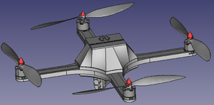
Detailed Design and Analysis
Combining the initial design selection and the requirements described previously, the team has determined the optimal design for the quadcopter. The frame of the quadcopter consists of 4 arms that are almost identical aside from a rectangular cut made in 2 of the arms to allow the camera board to pass through. Each arm has been hollowed out to allow the motor and Electronic Speed Controller (ESC) wires to be routed through them with the optional cover to be placed on top to increase the water resistance if flying in conditions that warrant it. Four mounting locations are present in each arm to allow M4 bolts to pass through them as an interference fit to reduce lateral movement and vibrations from the motors while flying.
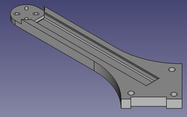
Figure 5: Arm of the quadcopter frame showing the rectangular cutout present in 2 of the 4 arms to allow the camera board to pass through the frame. After the arms were designed, FEA was completed using FreeCAD's FEA module FEM. FEM allows the part to be imported, meshed, and have forces and fixed constraints placed on various components of the part. For the arm, a mesh was applied to the body using the NMesh tool, with a maximum mesh size of 1000. Utilizing a mesh size that is too small will increase calculation time by the FEA software being used, often so much so that a result is never obtained due to the large number of nodes, while a mesh size that is too large will result in data that is not fully correct. A larger mesh size takes less time to compute due to the smaller number of nodes being analyzed. Using the NMesh tool, the maximum mesh size allows for a coarser mesh in areas with less complex geometry, while allowing a finer mesh to be applied to areas with more complex geometry. This allows areas such as the flat top surface to be calculated quicker due to the lower chance of stress concentrations, while areas such as the end of the arms with more stress concentrations are given the minimum condition, allowing a smaller mesh with more nodes to be applied to it. Constraints were placed at each hole location as well as the back edges of the part to simulate it being fixed between the top and bottom plate. After the constraints were placed, a force on the face at the end of the arm where the motor mounts (right) was placed with a magnitude of 15N, which is roughly the force the arms will experience during full throttle.
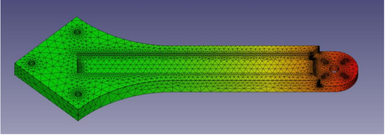
Figure 6: Displacement FEA results for the arms of the frame using FreeCAD's FEM module yielding a maximum displacement of 3.4mm and an average displacement of 1.53mm.
From the FEA results using FreeCAD's FEM module, it was determined that the absolute displacement of the arm was located on the end of the arm where the motor is mounted, with a maximum displacement of 3.4mm, and an average displacement of 1.53mm. This displacement will only be experienced for a very short amount of time, as once the quadcopter takes off, the rest of the frame begins to move with the motors, lowering the displacement significantly. Similarly, the Von Misses stress can be calculated using the FEM module, resulting in a maximum stress of 9611.4 kPa. When comparing this maximum stress to the tensile strength of PETG (the material the frame is made of), the tensile strength of PETG is 53 MPa.
Using the equation above, the factor of safety can be determined for the arm by dividing the ultimate tensile strength (53 MPa) by the found maximum Von Misses stress. This results in a factor of safety of 5.51. A factor of safety of 1 is the minimum required factor of safety, while a factor of safety of 2 is desired, meaning that the arms are strong enough to withstand the forces of maximum throttle flight.
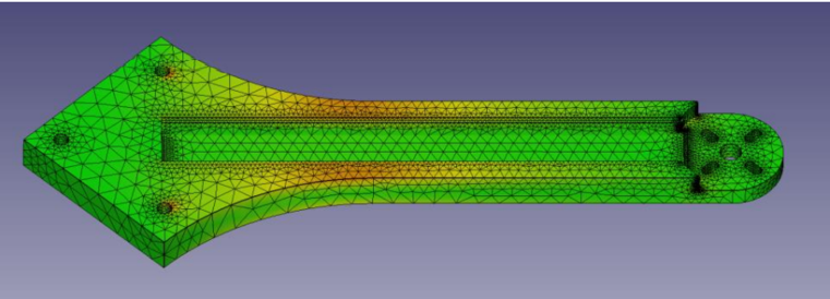
Figure 7: Von Misses FEA results for the arms of the frame using FreeCAD's FEM module yielding a maximum Von Misses stress of 9611.4 kPa. The remaining portion of the frame is made up of 2 plates and a cover. The bottom plate seen in Figure 8 houses the camera module with open space to add mounting points for additional modules. This bottom plate is held on using countersunk M4 screws which are passed through the arms, screwing into heat set inserts molded inside the top plate. To mount the camera onto the quadcopter, a protective box was created with 3 sets of mounting holes. This box will protect the camera in case of a crash landing in the event that the feet break away from the frame of the quadcopter. The multiple sets of mounting holes allow the camera to be angled downward at either a 45-degree or 90-degree angle. This lets the user record photos or video from an aerial point of view instead of straight on.
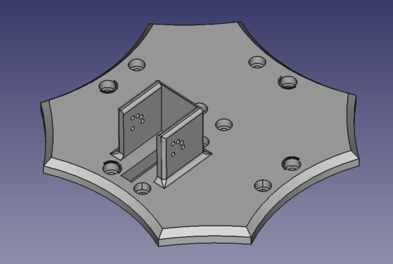
Figure 8: Bottom plate with variable position camera mount and countersunk mounting holes. The top plate has heat set inserts molded into it for each arm and has 4 standoff posts for bolting down the Arduino. The Arduino has been raised above the surface of the top plate to allow wires, IMU, ESCs, and receiver to be mounted below it. Figure 9 shows the top plate with all the components placed on it in their initial locations, while the final location of the receiver is located on top of the Arduino. The components placed below the Arduino are mounted to the top plate using double sided insulated tape. This insulated tape provides a barrier between the components and the molded heat set inserts to prevent shorting from happening. Using insulated tape also allows prevents the components from being hard mounted, as in the event of an in-flight failure or an uncontrolled landing, hard mounted components could snap at their mounting points.
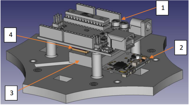
Figure 9: Top plate with Arduino (1), Camera Board (2), Receiver (3), IMU (4), and heat set inserts mounted. The next part of the frame that was created was the cover. This cover houses everything on the top plate and is held to the rest of the frame using 4 heat set inserts and 4 M4 screws. The sides of the cover are angled along a specific path to allow the propellers to spin freely without hitting the cover. This angle was determined using the FEA results from the arms, giving a minimum of a 4mm gap between the tips of the propellers and the cover to compensate for the maximum displacement of the arms, as well as any flex the propellers may experience.
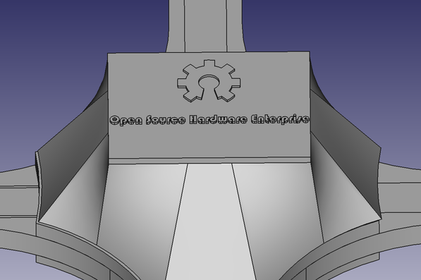
Figure 10: Angled cover to protect internal components and prevent propellers from interfering with the frame. The final part of the frame that was designed was the feet. These feet utilize the mounting locations of the motors, as the 4 bolts used to secure the motors are also used to secure the feet to the frame. These feet were designed with the intention to break before any other component as they are small and easy to replace. The feet were designed with a conical shape to provide rigidity with a slight outward bend to them to allow them to flex. These can be seen below in Figure 11.

Figure 11: Cinematography Quadcopter feet. Using the same FEM module as the arms, FEA was conducted on the feet to simulate a landing from 1m in the air. This impact testing was done by placing constraints on the top of the feet where they meet the underside of the arms, and a force was placed on the bottom of the feet. This test yielded a maximum displacement of 1.63mm and an average displacement of 35 micrometers. Because of the outward bend to the feet, this 1.63mm can be absorbed by the feet without failure.
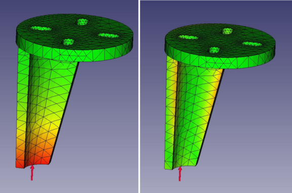
Figure 12: Absolute displacement (left) and Von Misses stress (right) for the quadcopter's feet.
Calculating for the Von Misses stress on the feet yielded the maximum stress on the entire frame, with a maximum stress of 31.59 MPa. Though these feet yielded a large Von Misses stress, the results are still below the tensile strength of 53 MPa. Like the arms, the FOS for the feet can be determined using the same equation, yielding a FOS of 1.68, which is above the minimum requirement.
Combining each of these parts, the frame was assembled using the previously described M4 screws and heat set inserts. The motors, propellers, Arduino, and the rest of the components can then be added as seen in Figure 13 below. The weight of the frame without any additional components was determined to be 411g, while the weight of the frame with components was determined to be 1088g. Because the total thrust of the quadcopter is required to be double the total weight, the quadcopter is able to safely fly and perform a vertical takeoff and landing safely.
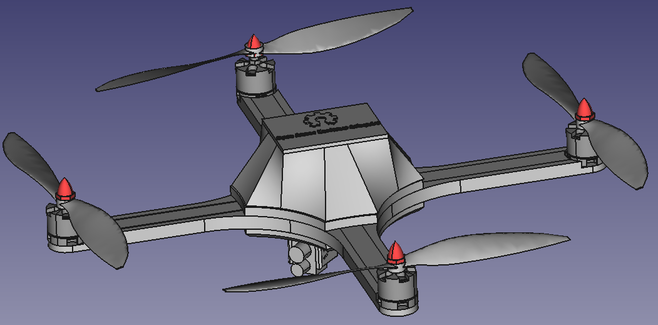
Figure 13: Completed assembly of the quadcopter with all components mounted including the optional arm covers.
Fabrication/Manufacturing
Once the frame of the quadcopter is designed using computer aided design (CAD), the files can be exported to a common format (STL or STEP) and 3D printed. 3D printing was the chosen manufacturing method as it is a common open-source option that many hobbyists have access to. 3D printing also allows the user to print the changes they make easily and quickly with minimal hassle. There are 3 common types of filaments used in 3D printers, Polyethylene terephthalate glycol (PETG), Acrylonitrile butadiene styrene (ABS) and Polylactic acid (PLA). PLA has the lowest strength of the three options and typically shatters upon impact, while ABS is stronger and tends to bend instead of break during impact, making it a more ideal choice for a quadcopter frame. The last option is PETG, which is stronger than ABS when it is printed using layer lines like how a 3D printer works6. Given that the frame should not flex and should remain rigid, the optimal choice is PETG due to its superior strength and rigidity. The properties for PETG can also be found in Appendix E.

Figure 14: PLA vs ABS vs PETG material properties8. Before a part can be printed, it needs to be "sliced", meaning that the part needs to be broken down into individual layers that it will be printed in. A 3D printer works by melting the chosen material into a thin strand, creating the part in many different layers. Once a full layer is printed, the 3D printer will move its nozzle upwards in order to start printing the next layer. When slicing the parts before printing, there are multiple factors that can affect the print speed, resolution, and strength of a part. The first setting that was adjusted was the quality of the print. A higher resolution will reduce the visibility of individual layers, but takes much longer to print, so a standard to high resolution was used for most parts. The second setting that was adjusted was the infill of the part. 3D printed parts are not solid, and are often partially hollow, filled with a certain pattern, in this case a triangular grid pattern. This was chosen as it increases the strength of the part when compared to a rectangular infill pattern, and the infill was set high to retain strength throughout the part, but reducing the overall weight, allowing for larger payloads to be carried. The final setting that was added was the use of support. Support allows for portions of the part to have overhangs or internal cavities that could not normally be done using traditional manufacturing methods. An example of this is the use of supports on the cover, where the mounting tabs create a negative cavity that cannot be made on any other machine. For this project, a Lulzbot Taz 3D printer was used as it provides a large build volume, 280mm x 280mm x 250mm, and provides good quality. Because a Lulzbot 3D printer is used, the Lulzbot version of Cura is being used as a slicer, which will import the STL files created from the 3D models, and slice the parts into individual layers, applying the chosen settings in Cura.
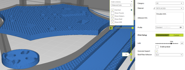
Figure 15: Cura slicer used to print each part using PETG and triangular infill. Once the parts are printed, excess support material can be removed, and the parts can be assembled. Figure 16 below shows the assembled parts without the motors, props, or electrical components assembled on the frame. The heat set inserts are inserted into the top plate and cover to allow the M4 screws to secure each part together, and the holes in the arms are undersized to create an interference fit to prevent lateral movement and vibrations during flight. This figure was taken during testing where the propellers are not attached to the motors for safety, and the center cover and feet are removed to make handling the electronics easier.
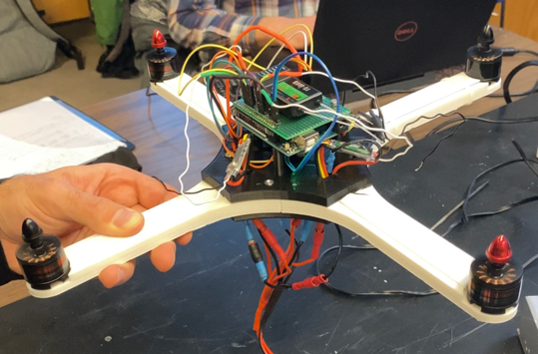
Figure 16: Assembled 3D printed frame with components excluding center cover, feet, and propellers during testing.
Coding and Electrical
After 3D printing and building the frame, each component can be attached and wired to the Arduino. Figure 17 below shows the wiring diagram for this quadcopter, where each motor runs to an ESC, which uses a Pulse Width Modulation (PWM) input on the Arduino to be controlled. A PWM input was chosen for many reasons, the first being its efficiency. A PWM signal will have a much smaller voltage drop when compared to a direct analog signal. This allows the motors to have an accurate voltage applied to them, allowing them to be used to their full potential. The second reason is that the signal remains digital throughout the entire circuit. A digital signal is important as it allows the motor to be controlled variably as an analog signal sends a simple on/off, while the digital signal allows for greater control. Using a PWM input also eliminated the need for resistors in series which causes further dissipation and decreases efficiency and control.
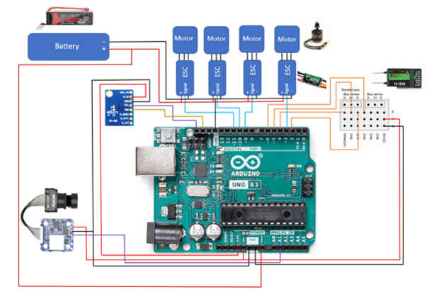
Figure 17: Cinematography Quadcopter wiring diagram.
With the motors connected to the ESCs, and the ESCs connected to the Arduino, Power and Ground as seen in Figure 17, the receiver can be connected to the Arduino to allow user inputs from the transmitter (handheld controller). This receiver requires a signal for each motor, as well as a power and ground from the 5V and ground pins of the Arduino. A similar series of events is also done for the Inertial Measurement Unit (IMU) to allow the quadcopter to read its position in space relative to each axis. The final component that is added is the camera. The camera is wired using a power and ground from the Arduino, with a signal wire tapped into the shutter button circuit controlled using an analog signal from the Arduino. Since the shutter button only needs activation with no control, an analog signal can be used, leaving further PWM inputs open in the event that an addition piece of equipment needs to be added.
Once the frame is 3D printed, testing can commence to confirm each component works as intended. To do this, the MultiWii software was used to control the Arduino. This software is open-source and allows the user to input various components into the code to utilize the predefined PID parameters. These components are inputted into the code by uncommenting the corresponding line as seen in Figure 18.
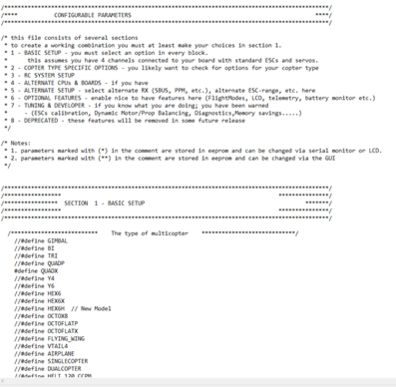
Figure 18: Config file in MultiWii allowing users to input components to simplify the coding process. Once the components are inserted or added to the code (in the case that a component is not listed such as the IMU being used in this project), the code can be uploaded to the Arduino. MultiWii comes preinstalled with a custom graphical user interface (GUI) which allows the Arduino to be plugged into a computer via USB and controlled virtually. This GUI can be seen below in Figure 19, where the IMU statistics can be seen on the left side while the transmitter (handheld remote) inputs can be seen on the right-hand side, represented by thrust, pitch, yaw and roll.
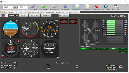
Figure 19: MultiWii main GUI showing the IMU statistics (left) and user inputs (right).
Testing and Validation
Once the initial wiring and code was completed, the quadcopter was tested. The initial testing was conducted without the propellers attached to the motor with the Arduino plugged into a computer to utilize the GUI statistics. Table 3 below show the testing matrix that was used for the initial testing to verify that the quadcopter was able to safely fly.
Table 3: Testing and Validation Matrix (P denotes passed)
| GUI
(ability to see response in GUI) |
Quadcopter
(ability to see/hear physical response on quadcopter) |
User Transmitter
(Ability to see response on the user transmitter) | ||
| Arduino Arms | P | P | ||
| ESCs Arm | P | P | ||
| IMU Response | P | P | ||
| Motor Response | P | P | P | |
| Receiver Response | P | P | P | |
| Camera Response | P | P | ||
Using this testing matrix, each component was tested through various tests relating to a response from the GUI, Quadcopter, and User transmitter. These tests ensure that all 3 inputs can either control or react to an action that happens. During testing, the GUI, quadcopter, and user transmitter were able to properly interact with each other resulting in the quadcopter having the ability to safely take off, hover, respond to various inputs and land. These results can be seen below in the following figures.
Utilizing this GUI, the quadcopter can be flown virtually to test each component. Doing this, the inputs from the transmitter were tested to ensure that the motors were responding properly. This was done by using the built-in serial plotter in the GUI, which converts the digital signal that is represented by numbers into a chart. This chart is seen below in Figure 20, where the response of each control movement is seen through the bars in the top right, while the PID parameters being used are shown in the top left. These PID parameters are determined using baseline values calculated using the MultiWii software, which will automatically adjust the parameters to achieve a stable flight.
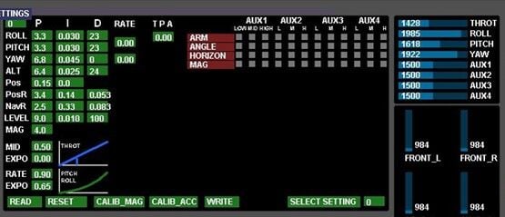
Figure 20: Input, motor, and PID testing results using the MultiWii GUI.
From these results, it can be concluded that the PID parameters are sufficient in controlling the quadcopter. While testing these inputs, the motors were connected to the battery to allow them to spin freely without the propellers attached. Adjusting the various inputs on the transmitter yields different responses in the chart. Each bar represents a different input (Throttle, Pitch, Yaw, and Roll), where this testing was done by adjusting each input to a different value to determine if the Arduino can handle multiple inputs at once. From this test, it was concluded that the Arduino Uno is sufficient in controlling the quadcopter, while the MultiWii software can achieve safe and reliable input management.
The second test that was done involved the response of the IMU. The IMU that was chosen is a 9 Degree of Freedom (DoF) IMU which will allow the quadcopter to determine its correct orientation at any moment. To test the responsiveness of the IMU, the MultiWii GUI was used to gather data, as the IMU data can be gathered similar to the input and motor testing. These results can be seen in Figure 21, as the quadcopter was rotated in multiple directions while the motors are connected to the battery.
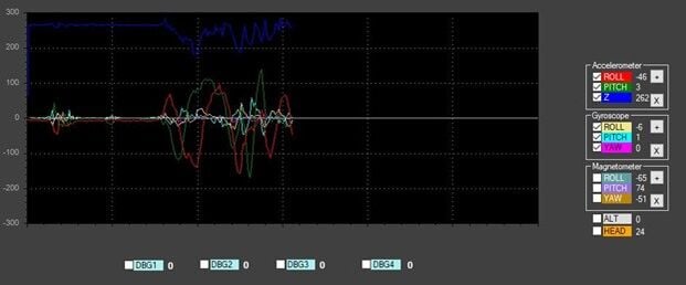
Figure 21: IMU testing results using the MultiWii GUI.
Like the input and motor testing, the chart at the bottom of Figure 17 shows the response from each DoF as a different color. During this test, no user inputs were given via the transmitter, requiring the motors to adjust using the PID gains to compensate for unexpected angle. From this test, the motors responded by attempting to return the quadcopter to a level position that was parallel with the ground, while the results gathered from the IMU showed accurate readings compared to our movements. As seen in the figure, the accelerometer readings were much larger than the gyroscope readings due to the motors attempting to correct the movements we made to achieve a stable hover.
The final testing that was done was to determine if the camera can be successfully triggered from the transmitter. To do this, the camera was wired according to the wiring diagram seen in Figure 17. One of the auxiliary switches for the camera was used to toggle the shutter button activation, sending either a photo or video to the SD card installed on the standalone camera board module. The goal of this test was to successfully gather a picture of the OSHE lab using the camera while attached to the frame of the quadcopter. The photo gathered from this testing can be seen in Figure 22, showing that the camera is able to be successfully controlled.
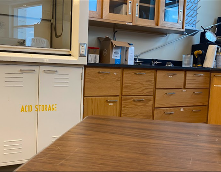
Figure 22: Picture obtained using the camera module on the quadcopter.
Conclusions and Future Work
This cinematography quadcopter integrates open-source software and hardware to create a foundation for the open-source community to build upon. This quadcopter utilizes a 3D printed frame using PETG to achieve the desired strength, although the design can be easily printed in other materials based on the needs of the application, while being designed using the open-source CAD software FreeCAD. The use of FreeCAD allows any user to make changes to the frame by changing the design, such as adding mounting locations for additional equipment without the need for specialty software. The frame was designed to achieve the maximum rigidity in the key components such as the arms and base plates, while other components were designed to flex and break under high loads. The arms were designed with a FOS of 5.51, allowing it to withstand large impacts before yielding, while the feet of the quadcopter were designed to take the impact load during landing by flexing. FEA was performed to determine resistance to a drop 1m above the ground, resulting in a FOS of 1.68, being the first component to yield upon impact. Because the frame was designed to be rigid, the main components had minimal displacement under load, while minimizing the weight of the quadcopter, increasing its ability to carry larger payloads.
Standard quadcopter components were utilized with the open source MultiWii software which allows for control over every aspect of the quadcopter. The MultiWii software allows the user to input the specific components being used, and automatically determines the proper PID gains to control the motors. This software also allows the quadcopter to recognize its position in space relative to each axis and make corrects automatically when it experiences unexpected angle. Utilizing this software, the quadcopter can fly safely and reliably with enough power to carry an additional payload.
To continue the design of this quadcopter, additional sensors could be added to increase the quadcopter's utility. The addition of a LiDAR sensor or altimeter will allow the quadcopter to achieve a stable hover without any user input by referencing either the ground or using GPS positioning to determine its altitude. Another addition to the quadcopter that can be implemented in future work would be the optimization of the frame in order to reduce its overall weight while retaining its strength. This can be done with specialty software such as Altair's Inspire software which allows the user to import geometry and automatically optimize it. This would allow the quadcopter to become much lighter utilizing unconventional geometry and modeling techniques. Because of the nature of the quadcopter being an open-source project, there are an infinite number of revisions that can be made to improve its design, and the participation by the open-source community will likely implement these ideas and carry the design further.
Further investigation into the fatigue life of the different components of the quadcopter will also determine which components need to be reworked in future iterations. The fatigue life of each component will determine how many take off or full thrust maneuvers can be done before the arms of the quadcopter fail. This required more research and testing of the PETG material to determine where the infinite life range lies and whether the maximum stress applied to the arms under full throttle lies inside this infinite life boundary. Fatigue strength can also be looked at to determine what the maximum stress is before failure at the life cycle of the part, guiding further iterations.
References and Research Findings
- Bhandari, A., Ahmad, F., Kumar, P., & Patil, P. P. (2019). (tech.). Design and Vibration Characteristics Analysis of Quadcopter Body Frame. International Journal of Applied Engineering Research. Retrieved March 2021, from https://www.ripublication.com/ijaerspl2019/ijaerv14n9spl_13.pdf.
- Javir, A. V., Pawar, K., Dhudum, S., Patale, N., & Patil, S. (2015). (tech.). Design, Analysis and Fabrication of Quadcopter. Journal of Advance Research in Mechanical and Civil Engineerin. Retrieved March 2021, from https://www.google.com/url?sa=t&rct=j&q=&esrc=s&source=web&cd=&ved=2ahUKEwjexdH8xM30AhXLG80KHVsXD64QFnoECAQQAQ&url=https%3A%2F%2Fnnpub.org%2Findex.php%2FMCE%2Farticle%2Fdownload%2F342%2F304&usg=AOvVaw06khR3MMLkmDOntZsxSDwj.
- Kuantama, E., Craciun, D., & Tarca, R. (2016). (tech.). QUADCOPTER BODY FRAME MODEL AND ANALYSIS. University of Oradea. Retrieved March 2021, from http://imt.uoradea.ro/auo.fmte/files-2016-v1/Endrowednes%20Kuantama%20-%20Final%20Quadcopter%20Bodyframe%20Model%20and%20Analysis.pdf.
- Parandha, S. M., & Li, Z. (2018). (tech.). Design and Analysis of 3D Printed Quadrotor Frame. International Advanced Research Journal in Science, Engineering and Technology. Retrieved March 2021, from https://iarjset.com/upload/2018/april-18/IARJSET%2011.pdf.
- Santiago, J. M., & Kasley, K. L. (2017). (tech.). Design & Development of a 3D-Printed Quadcopter Using A System Engineering Approach in an Electrical Engineering Masters Capstone Course (pp. 1–22). American Society for Engineering Education.
- Simplify3D Software. (2019, May 30). Properties table. All-In-One 3D Printing Software. Retrieved March 2021, from https://www.simplify3d.com/support/materials-guide/properties-table/.
- Yemle, S., Durgude, Y., Kondhalkar, G., & Pol, K. (2019). (tech.). Design & Analysis of Multi-Frame for Octo & Quad Copter Drones. International Research Journal of Engineering and Technology (IRJET). Retrieved March 2021, from https://www.irjet.net/archives/V6/i6/IRJET-V6I6596.pdf.
- Recreational Flyers & Modeler Community-Based Organizations. (2021, September 2). Retrieved December 10, 2021, from https://www.faa.gov/uas/recreational_fliers/.
- Dielectric Manufacturing. (2021, November 19). Material properties of thermoplastic PETG. Dielectric Manufacturing. Retrieved December 10, 2021, from https://dielectricmfg.com/knowledge-base/petg/.