This page details the process to adapt, install, and use the Marlin Firmware on an AthenaII delta-style 3D printer. The Marlin Firmware is a very popular and well supported open-source firmware used in a variety of commercial, reprap, and hobbyist printers. Marlin is written in C++ (Arduino Flavor) and utilizes a number of special features to maximize efficiency while minimizing program size. The Athena II is a delta-style 3D printer developed and Michigan Technological University and, by default, runs the Franklin firmware and controller package. This page will describe the necessary steps required to adapt your Athena II for use with Marlin with Octoprint as the controller.
This mod was first completed by TheJLo (talk) 05:13, 21 November 2019 (UTC).
If you have suggestions for these instructions or if anything is unclear, please discuss this in the Talk:Marlin on AthenaII or message User:TheJLo.
Warnings[edit | edit source]
This mod requires changes to the hardware, firmware and software of the Athena II. To do this on the original Athena II boards is risky and mistakes can break the board. It is recommended that you are comfortable with the following topics and skills before continuing.
- Soldering & De-Soldering
- Reading PCB Files
- Determining where a trace goes on a PCB
- Cutting Traces on a PCB
- Soldering wires to a PCB
- Usage of a Digital Multimeter
- Familiarity with electronics
- Familiarity with electrical communication
- Basic Linux
You are entirely responsible for your Athena II if you attempt this mod. If you are not comfortable with any of these topics, this mod may not be for you.
Making this mod better[edit | edit source]
In order to make this process easier, the AthenaII board will need to be redesigned. This would ease a large portion of difficulty in this mod as well as limit changes to just software and firmware.
An alternative solution would be to change Marlin to operate to the AthenaII board. While this might be possible, it may crop up other difficulties due to these changes.
If anyone has any other suggestions to simplify, clarify, or otherwise improve this mod, please feel free to mention them in the Talk:Marlin on AthenaII page.
Getting Familiar[edit | edit source]
Because we will be changing the hardware on the Athena II, it is recommended to get familiar with the Athena II board and how it works.
The following will describe how the system is setup to run Marlin. Take note of the changes in hardware required. The first thing covered will be the high-level setup we will be using.
System View[edit | edit source]
When running Marlin, the system will be fairly similar to that of the AthenaII when running Franklin. The board will be the physical control unit of the printer. On the ATmega1284P (The microprocessor on the AthenaII), a configured setup of Marlin will be installed. Marlin will expect commands to come in from the Rx/Tx0 UART on the ATmega1284P. These commands will come in the form of GCode from the controlling software. The controlling software will be installed on the Orange Pi which provides a front-end interface to the AthenaII Board. For this project, Octoprint will be used as the controlling software because it closely resembles how Franklin works and can be accessed remotely. A visual diagram of the system this shown below.

Marlin[edit | edit source]
Marlin is a firmware based off of Repetier. It is written in Arduino and is designed to operate with AVR chips. The newer version is also being designed to support ARM processors. Marlin is a reactive firmware meaning that it only completes actions based on requests from the controlling software or in response to changes in state on the electronics. Marlin expects to receive commands through a UART Serial line which is present on all AVRs which are Arduino-compatible. Marlin utilizes a system, appropriately called FastIO, to create direct references to the pins it uses on the AVR. This is a very robust and powerful system but has an important draw back.
Marlin can only run at pre-specified frequencies, ideally 16 MHz, for AVR microprocessors.
This FastIO system also needs to be told what pins go where on the AthenaII board. This is done with a "pins_ATHENA_II.h" file and a couple changes to the files pertaining to board definition. Marlin is also configured and calibrated using the files "configuration.h" and "configuration_adv.h". A basic Marlin setup with the necessary changes is available here: github. More information about Marlin can be found on their home site here: Marlin.
Required Hardware changes[edit | edit source]
Taking note of the required frequency for Marlin, there is a problem with the AthenaII. The AthenaII boards are initially setup to run the ATmega1284P microprocessor at 12 MHz which is incompatible with Marlin.
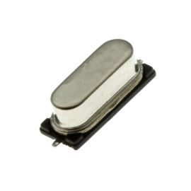
1. This necessitates that the AthenaII boards oscillator crystal is upgraded from a 12 MHz to a 16 MHz.
This is simply a swap of the crystal oscillator and its associated loading capacitors. However, another problem crops up from this change. The ATmega1284P is powered using a 3.3V in the default setup but when being run at 16 MHz will become unstable and cannot operate effectively.
2. This necessitates that the ATmega1284P be powered by 5V.
Luckily, there is already a 5V regulator on the AthenaII and we just need to cut out the 3.3V regulator and connect a wire from the 5V regulator. But again, there is another issue on the hardware that needs to be dealt with. Now that the ATmega1284P is being run at 5V, all of its logic signals will be output at 5V. The Orange Pi can only safely accept up to 3.3V logic from the ATmega1284P.
3. This means we need to step down all data coming from the ATmega1284P to 3.3V logic.
This can be done with a voltage divider and only needs to be applied to two pins: Tx0 and MISO on the ATmega1284P.
These are the required changes to the hardware to make our AthenaII boards Marlin compatible. This is the part that makes this modification difficult. All of these changes need to happen on the board with the layout given.
Required Software changes[edit | edit source]
Although Franklin uses a web-server front-end to talk to the printer, I am not sure if it is compatible with Marlin. Since getting Marlin up and running alone was difficult, I decided to use a proven controller which behaves similarly to Franklin's web server. This controller is Octoprint which is another web-server based front-end which can be used to control Marlin based printers. Installing and setting up Octoprint is fairly easy when following this tutorial. It might even work to control Franklin's firmware (someone should try that!) Using Octoprint, you can still control your printer remotely using the IP address and just adding port 5000 to the end of it.
Other than Octoprint, you will need some way to access your Orange Pi remotely, such as through PuTTy or SSH. We will also be using SCP (or PuTTy's equivalent) to transfer files to the Orange Pi. Finally, we will be using AVRdude to upload our programs to the ATmega1284P. AVRdude is used by Franklin as well so that does not need to be installed onto the Orange Pi. The Arduino IDE will be used to compile Marlin. You will want to install the latest version of the Arduino IDE onto your personal computer.
Instructions[edit | edit source]
The rest of this page will be devoted to the detailed instructions of how to complete this mod step by step. If you feel confident that you understand what you are doing and what the risks involved are, continue as you see fit. If you have any doubts, I do not recommend continuing. I (User:TheJLo) can answer questions, suggestions, clear confusion, etc. in the Talk:Marlin on AthenaII. These instructions will assume you are using a Linux system as a personal computer for some sections. Windows and MacOS should be similar with some locations changed.
Installing Octoprint[edit | edit source]
We will start with the simplest part of this process, installing Octoprint. This can be done while your printer is still assembled or completely disassembled. Installing Octoprint is also completely independent of the rest of this mod and can be done at any time. These instructions utilize this tutorial which is fairly clear and easy to understand.
Tools[edit | edit source]
- PuTTy/SSH
- Connection to the Orange Pi
Steps[edit | edit source]
- Connect to your printer via SSH (or PuTTy) (default User: debian, default Password: reprap)
- If you have not done so already, change the password with the following command. Follow the given prompts.
passwd - Follow this tutorial for the rest of setup: tutorial
- After setting up you should be able to load up Octoprint and add a printer with the following specs:
- Print Bed
- Form Factor: Circular
- Origin: Center
- Diameter: 210mm
- Height: 210mm
- Axes
- X: 3000mm/s
- Y: 3000mm/s
- Z: 3000mm/s
- E: 300mm/s
- Print Bed
- Once Marlin is installed, the Orange Pi will be connecting with the following settings:
- Serial Port: /dev/ttyS1 (Should be same for all Orange Pi Zeros. May not be for other computers.)
- Baudrate: 250000
Hardware Changes[edit | edit source]
This is where things get serious and is by far the most difficult part of this mod. After following any one of these changes, Franklin will no longer work on the AthenaII board. Make sure you know what you are going to be doing before you do it. Plan out your actions and take your time executing them. It is very easy to make a mistake here and some of these mistakes can be devastating.
Setup[edit | edit source]
Before starting to do any hardware modifications, the AthenaII board will need to be completely removed from the printer. At no time should you be making changes to the board while it is powered. The Stepper drivers should also be removed. Use the github containing the board files as reference when working. Get familiar with how the board is laid-out and practice finding components on the board from the board layout files. These are the tools that will be used for everything. The specific tools used for each major step will be listed again in each major step's tool section.
Tools[edit | edit source]
- Soldering Iron (Preferably with both a narrow tip and broad flat tip)
- Solder & Flux
- Solder Wick (Or your preferred solder removing tool)
- 16 MHz Crystal Oscillator or Ceramic Resonator
- 2 x Manufacturer specified loading capacitors (usually subtract ~2-5 pF from spec to account for parasitic capacitance)
- Hook-up wire (16-20 AWG works well)
- 2 x 1.8 kOhm Resistor (THT preferred)
- 2 x 2.7 kOhm Resistor (THT preferred)
- Digital Multimeter
- Isopropyl Alcohol (Higher % the better)
- Microfiber cloth
- KiCAD EDA Software link
- AthenaII Board Files link
Steps[edit | edit source]
- Disconnect Power supply from the AthenaII board
- Do not connect power without ensuring that ALL your changes are safe with the Multimeter
- The instructions will tell you where to probe and what the expected values will be
- Remove all wires from the AthenaII Board
- Unmount the AthenaII Board and Orange Pi from the mounting Bracket
- Carefully pull the Orange Pi and AthenaII Boards apart
- Should require a firm, but not excessive, amount of force.
- Try to avoid bending the pins. They can bend back easily but will wear down every time they are bent.
- Place the AthenaII Board at your Soldering work station
- Inspect for damage
- Clean with Isopropyl Alcohol as needed
- Store all other electronics and hardware in a safe place
Oscillator Swap[edit | edit source]
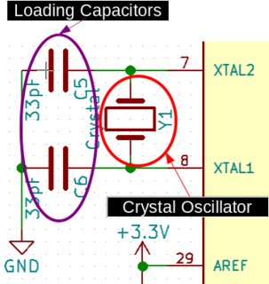
This series of steps will lead you through swapping the 12 MHz Crystal Oscillator with a 16 MHz alternative. Whether this 16 MHz is coming from a Crystal Oscillator or a Ceramic Resonator does not matter at this step. When flashing Marlin to the ATmega1284P, whether your using a Crystal Oscillator or Ceramic Resonator may matter, but that will be covered in that section. You must ensure that you use the correct loading capacitors (if needed). This can be determined by looking at the datasheet for your part. The manufactures specification will specify the Total capacitance which should be seen by the part. Typically, the value of your loading capacitors will be ~2-5 pF less than the spec. This accounts for the parasitic capacitance present in the board design.
-
Labeled schematic showing the Loading Capacitors and Crystal Oscillator on the Athena II
-
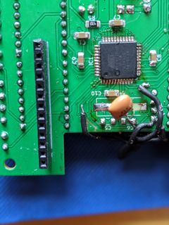
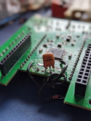
The final board with a pre-loaded 16 MHz Ceramic Resonator installed
Tools[edit | edit source]
- Soldering Iron
- Solder & Flux
- Solder Wick
- 16 MHz Crystal Oscillator or Ceramic Resonator
- 2 x Loading Capacitor
- Isopropyl Alcohol
- Microfiber cloth
Steps[edit | edit source]
- Heat and Wick Soldering Iron
- Desolder the two loading capacitors (C5 & C6) from the board
- Desolder the Crystal Oscillator (Y1) next to the loading capacitors
- Using the solder wick, soak up extra solder from the empty pads
- Clean the pads with isopropyl alcohol
- Solder on the new components
- Start with the oscillator (Y1)
- Then do each loading capacitor (C5 & C6)
- Make sure to get good solder flow over components
- Clean again with isopropyl alcohol
Testing[edit | edit source]
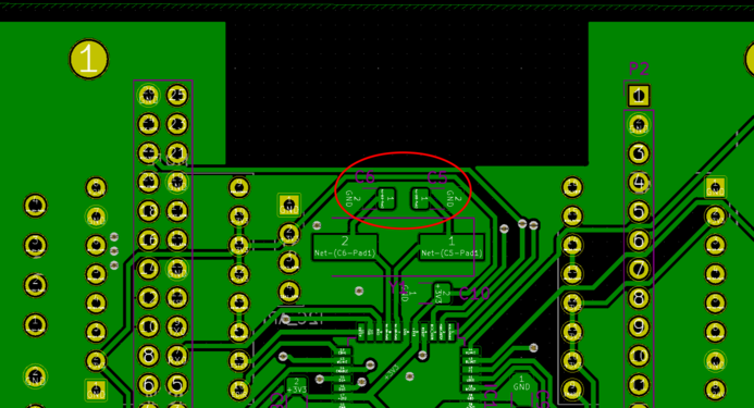
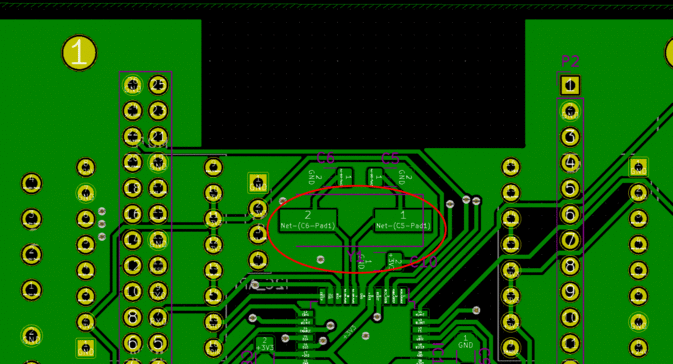
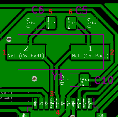
After soldering is complete, need to check that the connections are fine using a digital multimeter. Utilize the diagram and table below to verify each connection.
| Connection | Expected Resistance |
|---|---|
| 1 to 2 | > 500 kOhm |
| 1 to 3 | < 1 Ohm |
| 1 to 5 | < 1 Ohm |
| 1 to GND | > 500 kOhm |
| 2 to 4 | < 1 Ohm |
| 2 to 6 | < 1 Ohm |
| 2 to GND | > 500 kOhm |
