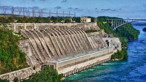
Hydropower is power that is derived from the force or energy of moving water, be it from the sea or from freshwater sources. It can be used to do mechanical work, or to generate electricity.
A hydro energy conversion system (HECS),[1] or hydro energy harvester is the term for the machine used to generate this mechanical or electrical energy from the captured energy of moving water.

Analyzing the available hydropower[edit | edit source]
Amount of waterflow and drop height; remoteness of the consumers[edit | edit source]
When a need of power emerges, we should seek one site or several sites that could host a hydroelectric powerplant. We understand that the research begins by identifying all sources of energy such as wind, solar, biomass and so on. Our proposition considers the conclusion of this inventory as preceeding the decision to install a hydroelectric plant, perhaps in addition to wind turbines or solar energy collectors.
A power plant demands a drop height and a waterflow (head loss). Terrain reconnaissance on the field or on topographic map pinpoints the locations of both waterflow and a slope of the terrain. These spots are easily identified on the ground where the river flows torrentially but other locations may also be appropriate. The extent of the drop is easily to determine for a surveyor by means of a theodolite. However, the estimation of the available waterflow is much more difficult because of its variation depending on the season (see average waterflow). It is wise to underestimate the rate available because the power plant should also not take off all water from the network. For example, in complete removal, the aquatic biotope will be severely disrupted by lack of water and make the spawning of fish impossible. Therefore, a reserve of waterflow should be left in the river to avoid biological depletion. It is possible that other -already authorized- water usages impose a higher reserve waterflow.
When several sites are identified, the remoteness of the consumer is another criteria for inclusion in the feasibility analysis. Remoteness means a longer power line and makes monitoring of the plant more difficult. An electrical power line represents a important expense and is a source of power loss.
Average waterflow[edit | edit source]
The amount of instantaneous waterflow of a river system depends on the amount of rainfall, which is dependent on the season. The instantaneous waterflow varies from day to day with a minimum thereof, located usually at the end of the dry season if it is marked. The concept of average flow has no interest in powerplants "along the waterstream"; however, it does allow one to better estimate the potential energy output of infrastructure if an accumulation is envisaged. Low water flow, i.e. the minimum flow of the river during 24h, determines the minimal power output potential of an installation. If the hydrological observations (measures of the flow of the river) are done for several years, it is possible to determine the average minimum waterflow attained annually, or it is possible to observe it every 5 years, or -even more rare-, every 10 years. Indeed, the severity of the drought is variable depending on the year. A flow measure during 365 days can not indicate whether the observed minimum is an exceptional speed (either low or high) or rather an average minimum. The hydrological data may be essential for the design of the proposed small hydroelectric plant. A lack of flow, and thus shortage of water, will lead to disillusionment when the installation is working due to the large gap between the expected power output and true available power. There is no need to seek accurate hydrological data if the power output of the proposed installation is well below the maximum power usage of the site chosen for the project. Given that the turbine is to be placed near the river, it is highly desirable to know the variations of water level to avoid seeing water invading the facilities during floods.
Measuring the flow rate and head for a stream[edit | edit source]
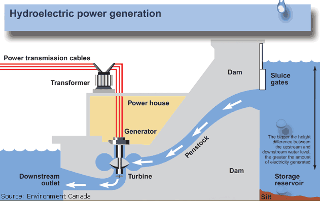
The slope of the channel, whether it is nearly horizontal or very steep, determines the available "head". Head is the difference in elevation between the point where you start capturing the water (beginning of stream or water diversion) and where you use it for energy conversion (where the hydroelectric system is set up). Different levels of head require different types of wheels. Systems requiring a high head include: Pelton and Turgo turbine, and backshot and overshot water wheels. Systems that require little head and a high flow are Crossflow turbines and breastshot water wheels. Finally, when there is no head available whatsoever (horizontal stream), a undershot water wheel can be used.[2]
The water flow is the rate at which water is moving through the stream at any given moment. The water flow must be consistent throughout the length of the stream (assuming the river has a input of water). Since a hydropower system uses the force of the water (dependent on its mass) and its potential energy (dependent on its height) to generate power, the flow rate is necessary when calculating the energy output of a hydropower system.
In order to assess the amount of flow and head available, it is necessary to measure them both. The height elevation can be measured using measuring tap or a height meter. The flow can be measured by building a temporary dam with a pipe. By filling a container with a known volume of water while measuring the time required to fill this volume with a stopwatch, we can determine the flow. For example, if we hold a five gallon bucket directly in the flow of a stream and it takes 4 seconds to fill up, we can determine that the flow is five gallons per four seconds, or 75 gallons per minute.
Mechanical power[edit | edit source]
Prior to the widespread availability of commercial electric power, simple mechanical power was produced and used for irrigation, and operation of various machines, such as watermills, textile machines, sawmills, dock cranes, and domestic lifts.
For 2000 years, waterpower has been harnessed to do useful work. Waterwheels played a vital role in early industrialization in Europe and North America, powering a wide variety of decentralized manufacturing and processing enterprises. The steel water turbine provided more power at a given site than the waterwheel, and in the U.S. many waterwheel-powered mills were converted to water turbines in the late 19th and early 20th centuries. Blacksmiths and foundrymen produced the turbines and modified the designs during this period of great innovation and profitable production. Water-powered mills produced: "... such household products as cutlery and edge tools, brooms and brushes... furniture, paper... pencil lead... needles and pins... watches and clocks, and even washing machines.... For the farm they turned out fertilizers, gunpowder, axles, agricultural implements, barrels, ax handles, wheels, carriages. There were woolen, cotton, flax, and linen mills... tannery, boot and shoe mills... and mills turning out surgical appliances and scientific instruments."
For centuries, power from hydroelectric resources has been captured by man: it is in 1688, that the MARLY machine, build from 14 wheels and pipes, allowed to pump back water from the Seine, located at an altitude of 162m, to supply in the needs of the ponds and fountains of Versailles.
Some of the work that it has been known to do is saw lumber, and grind grain. The water is usually transferred through a variety of ways; shafts, pulleys, wheels,cables and gears. Hydropower dates back to the Greeks who used vertical axis water wheels as early as 85 BC and horizontal axis wheels from 15 BC. The hydropower was the only source besides wind power to do useful work until the steam engine came along in the early 19th century.
Another method used a trompe to produce compressed air from falling water, which could then be used to power other machinery at a distance from the water.
Hydropower example[edit | edit source]
To calculate the theoretical maximum energy that can be produced from a microhydro plant, a few pieces of information are needed. Among these is the Hazen-Williams equation, which allows for the calculation of loss due to friction. The equation is as follows: f=0.2083*(100/c)1.852*Q1.852/d4.8655, where c is the hazen-williams coefficient and is unique to the piping used, Q is the flow in gallons per minute, and d is the diameter of the pipe in inches. The hazen-williams coefficient c is an indicator of how "smooth" the inner wall of a pipe is; since c is in the denominator, a higher c value correlates to less friction.
For instance, to find the friction loss of a 500 gpm flow through an 8" PVC pipe with a c value of 150, the Hazen-williams equation provides a loss of 0.613 feet-loss per 100 feet pipe. Once you have found the feet-loss per 100 feet of pipe, you can multiply this rate by the length of pipe to determine the total feet-loss. You would then subtract the total feet-loss from the total head to find the net head H that you will use in your final power output calculation.
To determine the power output of such a system, the equation P=Q*H/k is used, where Q is the flow rate in gallons per minute, H is the head loss in feet, and k is a constant of 5,310 gal*ft/(min*kW). For a flow of 500 gallons per minute and a head loss of 60 feet, maximum power would be found as: (500 gal/min *60 feet)/5310 gal-ft/min*KW, which comes out to 5.65 kW.
This theoretical maximum is prevented by real world obstacles, such as turbine efficiency, pipe friction, and the conversion from potential to kinetic energy. To determine how much energy can be produced by a plant with a given efficiency, simply multiply the theoretical by the plant's efficiency. Turbine efficiency is generally between 50-80%. For instance, if the same plant had 90% efficiency, 5.65 kW*0.9= 5.085kW.
Hydropower plants[edit | edit source]
Types[edit | edit source]
- Wave power plants (mechanical and electrical generator equipped)
- Tidal power plants (mechanical and electrical generator equipped)
- Tidal stream power plants (mechanical and electrical generator equipped)
- Ocean thermal energy conversion systems (mechanical and electrical generator equipped)
- Osmotic power plants (mechanical and electrical generator equipped)
- Vortex power plants (mechanical and electrical generator equipped)
- Continuous flow power plants (mechanical and electrical generator equipped)[3][4][5]
Note that the top 4 energy conversion systems are ocean energy conversion systems' (use in open sea), the osmotic power plant is used where sweetwater and saltwater converges (ie river mouths ending into the sea) and the lower 3 energy conversion systems are used in (freshwater) rivers, streams or on basins/ponds.
Categorization of freshwater power plants[edit | edit source]
Category: plants can also be classified as "along the waterstream" or "other". The first, "along the waterstream" receives water from the river or stream without accumulation infrastructure (dam, pool, pond...). The volume of water available for the turbine depends on the instantaneous waterflow of the river.
References[edit | edit source]
- ↑ Hydro and Ocean energy conversion system terms
- ↑ Practical self-sufficiency by Dick and James Strawbridge
- ↑ River current energy conversion system term
- ↑ Tidal energy conversion system term
- ↑ Wave energy conversion system term
- Village Earth: Do it yourself hydro power plant: Energy from Water / Hydropower
- Plans and manufacturers of hydoelectric plants
See also[edit | edit source]
- Comparison of bladed rotors for HECS
- energy harvesting
- Wind energy conversion system
- Tides
- Fish ladder