This modification is a part of the Kijenzi Project [1]
The purpose of this modification is to create a base for controlling the climate of the build-space. The primary focus of this modification thus far is to create a positive pressure within the build-space by closing off the printer and including a large, constantly running fan on the top of the printer. With the addition of a filter on the fan, this can reduce both dust and humidity within the printer. This design is also fairly insulated so that with the future addition of a heated bed, the temperature in the build space can be kept uniform for better quality prints.
Using your MOST Delta Printer, print the following components:
Item
Quantity
Corner Brackets
6
Hinge bottom
2
Hinge top
2
Magnet Brackets
2
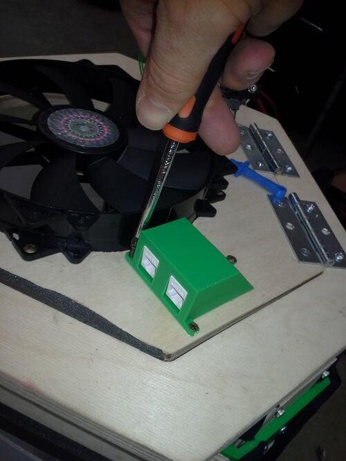
Ethernet housing
1
Handles
2
The stl and FreeCad files for these designs can be found at youmagine
Recommended Print settings for all components:
Layer Height: 0.20 mm
Shell Thickness: 1mm
Bottom and Top Thickness: 2mm
Fill Density: 20%
Print Speed: 50mm/s
Print Temperature: 185C
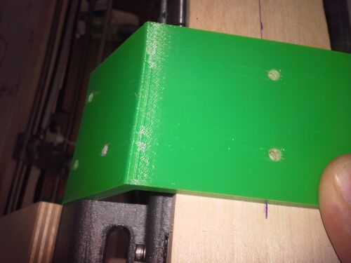
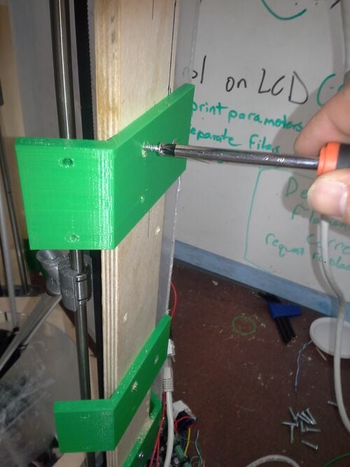
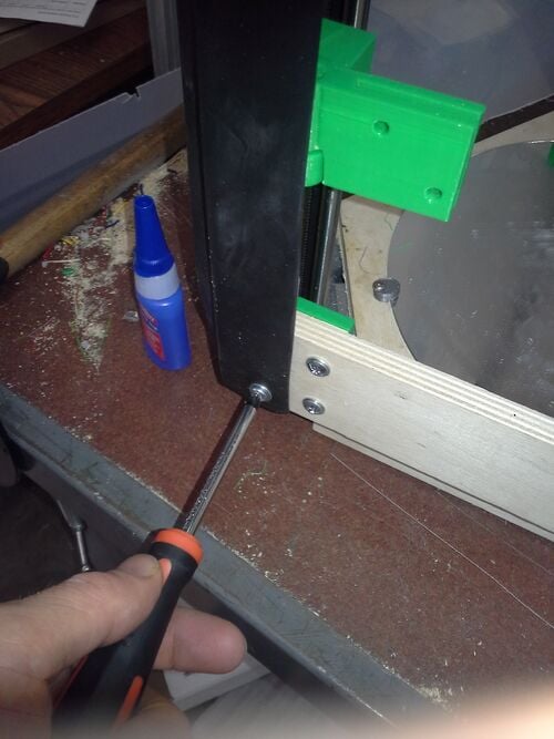
Attach the brackets to corner brackets to each of the the plywood sides using 2 #8 3/4" self drilling screws. Make sure the holes on the bracket are centered. Also ensure that the top bracket is flush with the underside of the top PLA corner piece of the Athena printer and that the bottom bracket is placed approximately 2.5" from the ground.
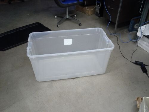
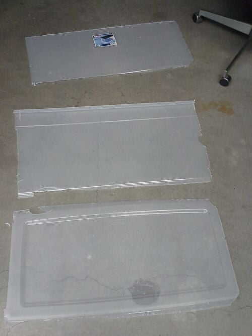
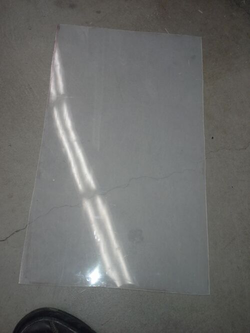
Prepare the polypropylene sheets by ensuring that they are the correct size to be placed over the brackets. If you cannot find polypropylene sheets, you can cut a bin into pieces as seen in the picture.
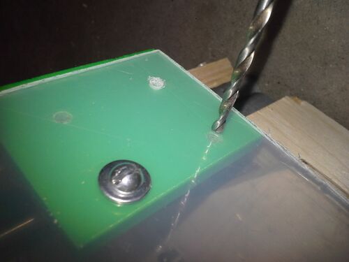
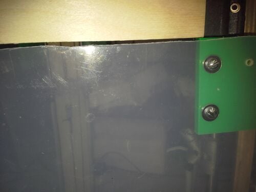
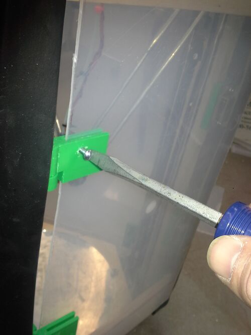
After aligning the polypropylene (PP) sheets to the corner brackets, using a power drill and a 1/8" bit, drill holes through two of the PP sheets in the locations of the holes seen in the brackets.
Attach these two pp sheets to the brackets using the #8 1/2" machine screws and accompanying washers. Make sure that the PP sheets are attached on the OUTSIDE of the corner brackets. Only use two 1/2" inch machine screws per corner, only using the inner holes.
On the remaining side with no polypropylene sheet, attached the two 6 cm x 30 cm x 13 cm board to the corner brackets by pre-dilling holes and using the #8 1 inch Machine screws. Ensure that these are flush with the top and bottom brackets
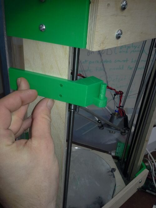
Attach the hinge bottoms to the wooden support to the left of the open side of the printer. In the distance between the top and bottom bracket (approx 40cm) you should center the hinge at about 13 cm (1/3 of the way) and the other at approximately 27cm (2/3rd). Do this with the 1/2" flathead screws
Do the same with the magnet brackets on the opposite side.
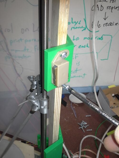
Place the top hinges onto the bottom hinges and attach the magnet latched to their brackets with 3/4" self-drilling screws. If the hinges do not go on easily, sand them down first
Cut the 24" basswood pieces to a length of 40mm, and on one side, line the perimeter with the rubber-foam weatherseal.
Attach the basswood pieces over the hinge brackets, the magnet brackets, and the empty third side with two 1/2" wood screws.
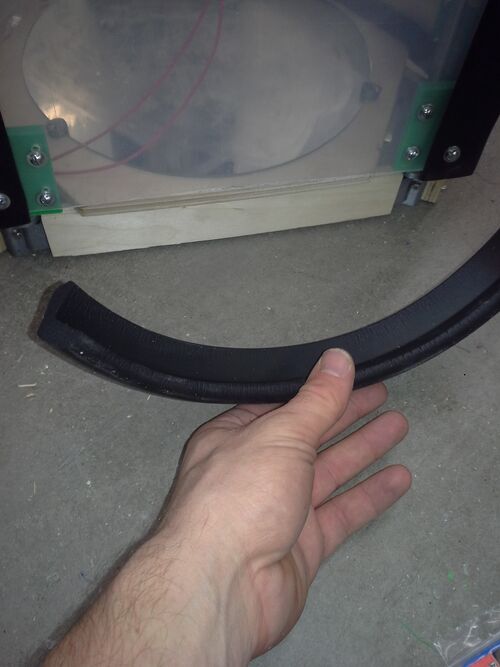
Cut the Nail-on EPDM rubber into 2 foot strips
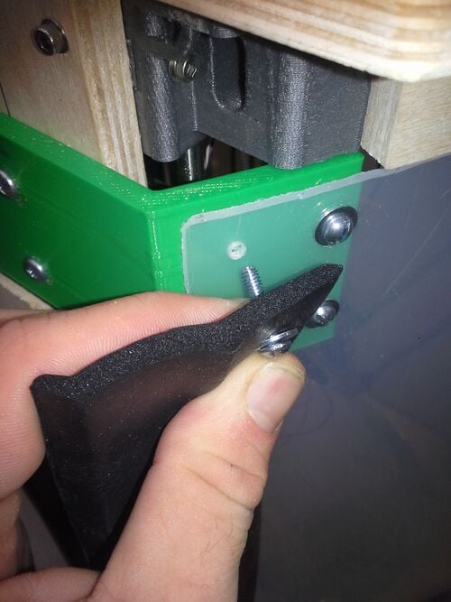
Using a 3/4" inch self-drilling machine screw for the open side and the 3/5" machine screws on the closed sides, attach the EPDM strips vertically along the corners. For the closed sides, place the machine screws through the outermost remaining bracket hole.
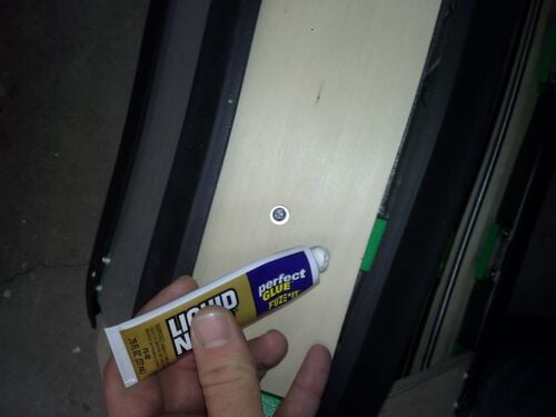
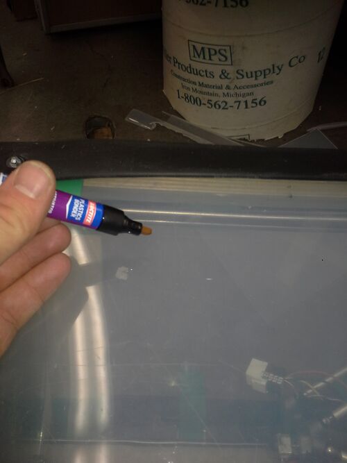
Glue the length of the strips onto the wood and PLA brackets with super glue and onto the polyproprylene with the plastic bonding agent.
Cut what remains of the strip into 1.5" sections and use superglue to attach it to the gaps between the top of the platform and the rest of the assembly.
Cut the last sheet of PP into a 40cm x 25cm section and place it into the space made available for it in the hinges.
Drill holes into the PP using the hinge brackets as a template. Use 1/2" machine screws to hold it into place.
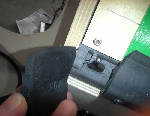
Do the same with the handles. Placing them roughly over the magnets.File:Kijenzi50.jpg
If extra seal remains, you may use it to seal the bottom by wedging it into the space between the printer base and the bottom of the polypropylene sheet
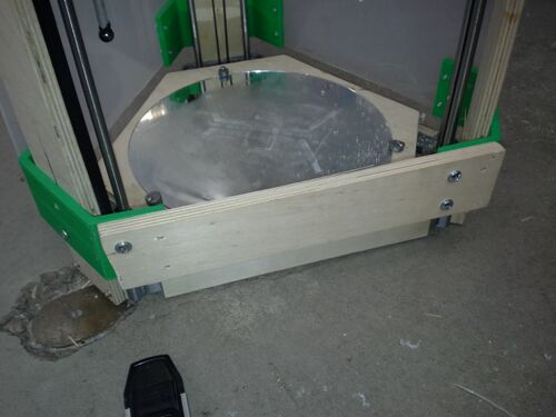
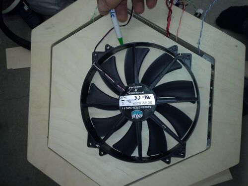
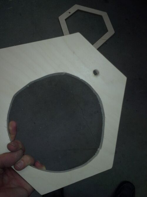
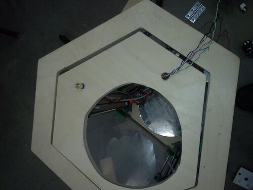
Take the hexagon plywood piece and trace the outline of the fan onto it.
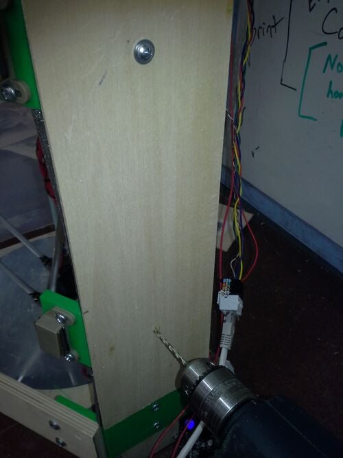
Using a jigsaw cut out the outline of the fan, and use the half and quarter inch drill bits to make holes for the wiring and tubing to pass through.
Thread the filament feed and wires though the appropriate holes.
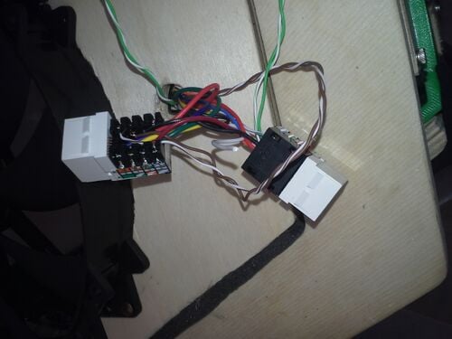
Using the female cat5 connectors sort out all of the wiring (other than the hot-end and U, V, and W stepper motors) including the wiring for the fan, into the ethernet ports. BE SURE TO REMEMBER AND NOTE WHICH WIRE GOES INTO WHICH PORT!
Use 1/2" screws to secure the fan, 2 hinges, and the ethernet ports to the top of the platform


