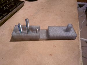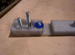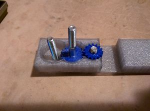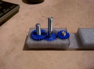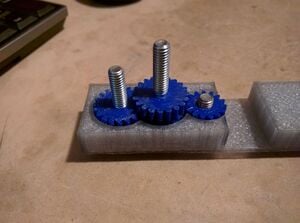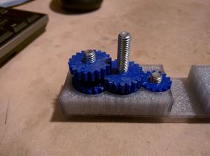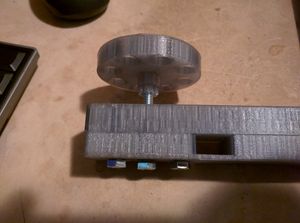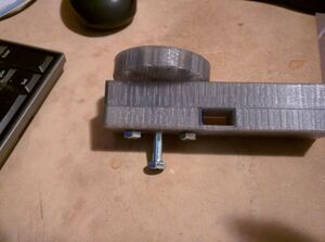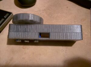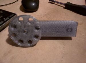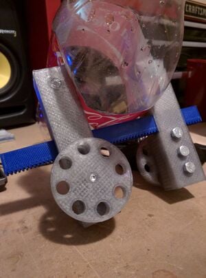
A clamp is used in many stages of manufacturing and assembly. Holding things in place during these processes will yield higher quality parts and enable more complicated pieces to be built. By using a geared system, much more force can be placed on objects compared to an un-geared clamp. Cost efficient and expandable geared clamps will help enable growth in technologically deficient countries.
Bill of Materials[edit | edit source]
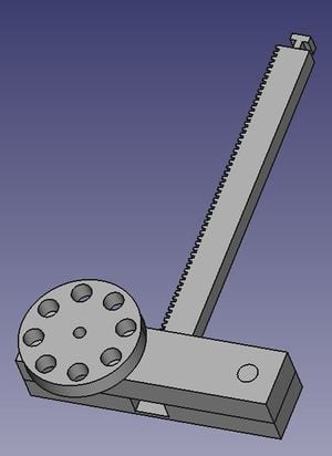
The clamping system is made up of the rack, and clamps. You will need two of the clamp assemblies for it to be useful.
- Clamp Assembly
- 1X Base ~26 grams PLA or ABS
- 1X Cover ~36 grams PLA or ABS
- 1X Handle Gear ~17 grams PLA or ABS
- 1X Pin Gear ~2 grams PLA or ABS
- 3X Reduction Gear ~2 grams PLA or ABS
- 1X Spacer Gear ~1 gram PLA or ABS
- 1X 20mm M6 ~ $0.53
- 1X 30mm M6 ~ $0.65
- 1X 40mm M6 ~ $0.70
- Rack Assembly
- nX Rack ~22 grams PLA or ABS
Clamp STL[edit | edit source]
- File:Geared clamp base.stl
- File:Geared clamp cover.stl
- File:Geared clamp handle gear.stl
- File:Geared clamp pin gear.stl
- File:Geared clamp reduction gear.stl
- File:Geared clamp spacer gear.stl
Rack STL[edit | edit source]
Freecad Source[edit | edit source]
- Source is available at http://www.thingiverse.com/thing:1183306
Tools needed[edit | edit source]
- MOST Delta RepRap or similar RepRap 3-D printer
- X-acto Knife
- Drill with 6 mm drill bit (may not be neccesary for extremely well calibrated printers)
- Pliers are also helpful
Skills and knowledge needed[edit | edit source]
- Know how to plasti-form with a bolt. (Screw into undersized hole to imprint threads).
Technical Specifications and Assembly Instructions[edit | edit source]
Prototype parts were printed in PLA with the following settings on a MOST Delta:
- Print Speed: 110 mm/s
- Temperature: 210 C
- Layer Height: 0.15 mm
- Infill: 30%
- Nozzle Dia: 0.5 mm
Printing (Based on settings above in cura (usually a high estimate))[edit | edit source]
- Base ~1 hr
- Cover ~1.5 hr
- Handle Gear ~1 hr
- Pin Gear ~10 min
- Reduction Gear ~10 min
- Spacer Gear ~5 min
- Rack ~45 min
Pre-Assembly ~20 min[edit | edit source]
- Use X-acto knife or deburring tool to remove flashing on all parts.
- Use drill to open holes in all gears except the handle gear. Also open holes in base (do NOT open holes in cover).
- Use the pliers and 40 mm bolt to plasti-form threads on the handle gear.
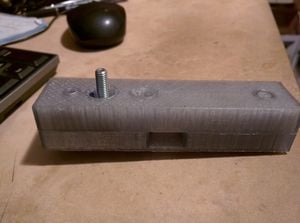
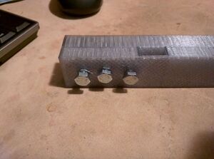
Assembly ~10 min (See pictures to the right)[edit | edit source]
Use[edit | edit source]
- Place rack in slot of clamp with gears towards the bolt side of the clamp.
- Rotate the knob so clamp drive grabs onto the rack teeth. Try the other direction if its not working.
- Pro Tip: use a pencil with the end stuck in the handle holes to enable quick, continuous turning of the wheel.
- This will also work as geared separators.
- This may also work for linear positioning systems that allow small changes in position like those used in optics.
Common Problems and Solutions[edit | edit source]
- Depending on printer calibration, the hole sizes can be too big or too small. Being smaller is actually preferred as it will aid in plasti-forming the threads. I printed at 1% undersized and had good results.
- Chaining racks can be tough if there is flashing around the part. Be sure to remove flashing before smashing 2 racks together.
Modifications[edit | edit source]
- 6 mm bolts are used as the shafts in this design, but there is nothing stopping use of other materials if the bolts can not be easily sourced. 3D printed shafts may work as well as wood dowels. The shafts could be fixed in place by melting the case plastic around the new shaft.
- The casing has a 10 mm hole that enables locking when the handle gear is aligned with it and a pin is inserted. Could be 3D printed, pencils work well too.
Cost savings[edit | edit source]
- If your solution is not a low cost one then it is not really appropriate.
At time of printing, 1kg of PLA cost ~ $23. At that rate, a system with 2 clamps and 1 rack would cost $4.55 in plastic and 3.76 in bolts. Total cost of $8.31.
This type of gearing is not common in commercial clamps, but clamps of similar size cost from $10~$20. Unlike commercial clamps, the range can be extended by printing more racks and chaining them together.
Cost savings $1.69~$11.69 or 17%~58%.
Area's for price reduction:
- Use cheaper shaft material
- Design static clamp end that requires no shafts, therefor only 1 geared clamp in necessary.
Current Issues[edit | edit source]
- Chained racks will have a double tooth in the center, this prevents a clamp from crossing center. Find a way to remove half a tooth in freecad...
