
3D Printed Micromanipulator


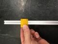
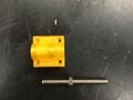
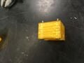
Picture of the parts required to assemble the micromanipulator.

Bill of Materials
[edit | edit source]- 3 pieces of OpenBeam, 75mm long.
- 3 pieces M5 threaded rod, 65mm long.
- 3 M3 x 10mm flat head socket screws.
- 6 M3 x 6mm socket head cap screws.
- 4 M3 x 20mm flat head socket screws.
- 4 M3 x 25mm socket head cap screws.
- 15 M5 hex nuts.
- 6 MR105zz roller bearings (NOT PICTURED).
- 3 printed knobs.
- 3 printed straddle ends.
- 2 printed straddle carriages.
- 1 printed vertical straddle carriage.
Assembly
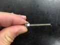
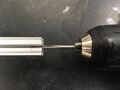
[edit | edit source]- Jam M5 nuts on one end of each of the threaded rods, chuck into a drill and remove burrs from the threads by rotating in #600 emory cloth or sandpaper.
- Thoroughly clean the threaded rods and 3 nuts with alcohol in a sonicator for 5 minutes.
- Run a 2.5mm drill bit in the holes for the captive nut retainer screws.
- Run a 5mm drill bit through all of the leadscrew holes in all the straddle ends and straddle carriages.
- The carriages should be very snug on the OpenBeam, but should slide reasonably easily. Run carriages back and forth on a long piece of OpenBeam until they slide easily.
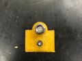
- Line up the MR105zz bearings with their pockets in the straddle ends and run a M5 x 40mm screw them and the straddle end. Place the screw head on the side with the deeper pocket. Place a nut and washer on the M5 screw and tighten to pull in and align the bearings in the straddle end.
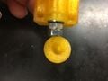
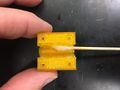
- Use the same technique to pull the captive nuts into their pockets in the straddle carriages.
- Thread the M5 x 6mm captive nut retainer screws into the straddle carriages. Do not tighten the screws!
- Tap threads into the carriage holes with the M3 tap or by "plastiforming" threads simply by running a screw into them.
- Thread a single nut onto each of the leadscrews.
- Ensure that enough thread extends from the back of the straddle end to engage two more nuts.
- Hold the properly positioned nut in place while starting the jam nut. Tighten the jam nut in place.
- Again check that there is sufficient threaded rod extending from the end of the straddle end. Adjust if necessary.
- Jam nut the free end of the threaded rod.
- Tap one end of each of the OpenBeam pieces with a M3 tap.
- Gently tap the threaded end of a piece of OpenBeam into each of the straddle ends. Secure in place with a M3 x 10mm flat head socket screw.
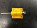
- Align the flats on the jam nut and the pocket in a knob and gently tap the opposite end of the threaded rod to engage with the knob.
- Countersink the four holes on the OpenBEam side of one of the carriages (not the vertical carriage). Insert the M3 x 20mm flat head socket screws into the countersunk holes. This is the Z-carriage
- Apply a light coating of grease to the interiors of the carriages.
- Align the captive nut with the threaded rod and slide the carriages onto the pieces of OpenBeam.
- Advance the carriage until the threaded rod is all the way through the carriage and then tighten the captive nut retainer screws.
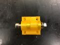
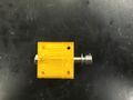
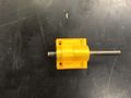
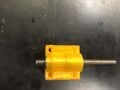
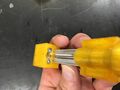
- A completely assembled axis should look as pictured.
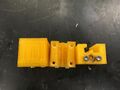
- The completely assembled axes should look as pictured.
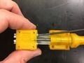
- Connect the straddle end of the Y axis to the straddle carriage on the X-axis with the four M3 x 25mm socket head capo screws.
- Attach the Z-carriage to the Y-carriage with the four screws that were inserted into the Z-carriage. Tighten the screws step-wise, rotating through each screw to avoid breaking one of the carriages.
-
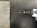 1. Remove burrs from threaded rod.
 -
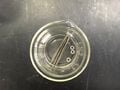 2. Thoroughly clean threaded rod and 3 nuts.
 -
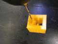 3. Run 2.5mm drill through captive nut retainer screw holes.
 -
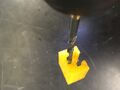 4. Run a 5.5mm drill bit through leadscrew holes.
 -
 5. Slide carriage up and down a long piece of OpenBeam.
 -
 6. Pull bearings into pockets with M5 screw.
 -
 7. Pull captive nut into carriage.
 -
 8. Thread in, but do not tighten the captive nut retainers screws.
 -
 9. Thread a single nut onto the lead screw.
 -
 10. Check position of nut.
 -
 11. Start jam nut.
 -
 12. Check the position again.
 -
 13. Jam nut free end.
 -
 14.. Tap OpenBeam end with M3 threads.
 -
 15 Screw OpenBeam in place.
 -
 16. Align flats on outer nut and knob and tap into place.
 -
 17. Install screws in one of the carriages. This is the Z-carriage.
 -
 18. Apply a small amount of grease to carriage interiors.
 -
 19. Slide carriages onto OpenBeam.
 -
 20. Tighten retainer screws.
 -
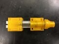 21. Assembled axis.
 -
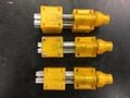 22. Completed set of axes.
 -
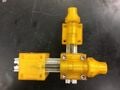 23. Connected X- and Y-axes.
 -
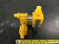 24. All axes assembled.


Assembled piece
[edit | edit source]| Authors | |
|---|---|
| License | CC-BY-SA-3.0 |
| Cite as | Gcanzalo (2017–2025). "3D Printed Micromanipulator". Appropedia. Retrieved July 25, 2026. |