
User:Jganoza

| Name | Joaquin Ganoza |
|---|---|
| Affiliations | |
| Location | |
| Nationality | |
| Interests | 3D printing, OSH, OSHE, Growbot, CAD, Motorcycles, Robotics, Automobiles, Traveling |
| Registered | 2019 |
Hi there, my name is Joaquin Ganoza. I am currently pursuing a Mechanical Engineering degree and have obtained my minor in International Spanish. I love to design and create using CAD and fabrication. In the past I have worked as an Mechanical Engineering Intern for the GLRC and this coming summer I will be an R&D Engineering Intern at Precision Planting.
Email: jganoza@mtu.edu
https://www.linkedin.com/in/joaquin-ganoza-667800128/
Experience
[edit | edit source]- Developed bespoke solution for mounting floor scanner in Yamaha Waverunner
- Past experience building several car engines
Enterprise
[edit | edit source]Semester 1 Fall 2019
Growbot:
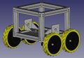
This semester I worked on OSHE's newly funded EMI project, Growbot. For this semester, I was tasked to be the design lead for the robot. I was the one responsible for designing the robot in CAD and bringing it to life with parts designed within that software. The software chosen to remain in the open-source community was FreeCad, utilizing both its part and assembly modules to design and incorporate parts together one unit. The robots frame went through multiple iterations until as a team we decided on a design that would best fit our needs for future endeavors we expect to do with this robot. I worked with the electronics side of the team to determine the layout of components within the robot, as weight distribution would be a key part of how the robot handles. After establishing the location of internal parts, I built the frame around that initial chassis to tie the robot together . The frame is designed to be easily taken apart with a screwdriver, allowing maintenance to be an easy task along with ensuring others will have an easy time to build the frame pieces if chosen to be replicated. Currently I am working on 3D printing the rest of the components that complete the robot, such as the tank Tracks, Rail Frames, Guide Wheels, and Gearing.
-
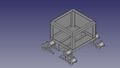 GrowBot CAD
 -
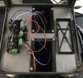 Internal Assembly
 -
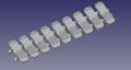 Tank Track Assembly
 -
 External Frame Assembly


Semester 2 Spring 2020
Growbot:
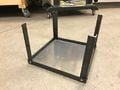
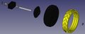
This semester, Zach and I took on the task to redesign the chassis for Growbot. Aluminium extrusion was chosen to allow for a symmetric and modular design that would allow for multiple types of sensors and attachments to be easily added. Following the chassis redesign, the next assembly that was changed was the drivetrain. We temporarily shifted away from the tank-track design to a more traditional wheel/tire setup. This setup would allow for us to easily change gearing, wheel/tire size, and tire tread design. With this simple hub design to carry the axle assembly, and with the majority of the pars within the assembly being 3D printed it would allow a user to easily be able to change parts on the fly to their liking. In this assembly, I designed a first set of test tires with PTU, otherwise known as NinjaFlex. This allowed for me to design different tread patterns on the tire to adapt for different terrain and also provide a softer ride for the robot since the material is flexible. Overall this redesign allowed for us to have a much sturdier, and reliable robot that could be produced in an easier manner compared to the old design. Light amounts of metal work had to be done in preparation for assembly like cutting the axles and aluminum extrusion down to size, but besides that its simple tools to assemble the robot. Assembly instructions for the robot can be found broken down into separate subsections in the OSHE Growbot page.
Main Growbot Assemblies
-
 Updated GrowBot CAD
 -
 Axle-Assembly CAD
 -
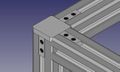 Corner joints and Extrusion


3D Printed Growbot Parts
-
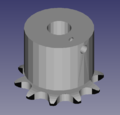 9-tooth drive gear
 -
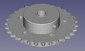 72-tooth driven gear
 -
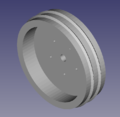 GrowBot Wheel
 -
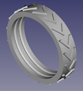 GrowBot Tire
 -
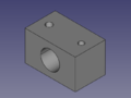 Bearing Hub


Semester 3: Spring 2021
This semester I worked alongside Dylan Mercier and Harris Neil in the early development of the cinematography quadcopter. The goal for this semester was to develop a frame that satisfied all the criteria and begin preparing the wiring harness to go into the drone. While Dylan developed the main CAD components and Harris developed the flight program, I shifted my focus on understanding and developing the correct wiring harness for main power and accessories of the drone. Since the design is based around the usage of an Arduino Uno as the controller, proper power distribution to such unit must be achieved while also properly powering the ESC's and Motors. This was achieved by managing the voltage coming into the board with the use of resistors and and a diode to create the proper voltage drop for the Arduino to manage. The ESCs and motors are directly connected to the battery and are managed through signal directed by the Arduino. The receiver outputs are routed to the PWM pinouts on the Arduino while the IMU inputs are received through the Analog inputs on the board. As a team we reached our goal for the semester of completing CAD of the drone but are still creating the final harness due to wait time on parts and Covid-19 complications.

Semester 4: Fall 2021
This semester Dylan Mercier and I worked towards finalizing and testing the cinematography quadcopter. I focused my work this semester into the wiring of the drone for all necessary modules and the code developed to drive the motors. A final wiring harness was created to following the schematic in the image below to implement the updated receiver, IMU and motor controllers. Once the harness was implemented and communication between the controller and receiver was established, initial testing was done on the IMU and ESC parameters. The IMU follows an initial calibration procedure that allows for the user to establish the orientation of the drone which is crucial as the IMU has control over the motors for stable hover during flights when user inputs are not being recognized. Following the IMU calibration, parameters for the ESC were set within the GUI developed for the drone. This meant establishing high and low parameters for the Yaw, Pitch, Roll and Throttle so when the drone is armed and active to will not fly away. Following that setup, PID values within the code were adjusted to accommodate for the type of flight being aimed for. The GUI comes with a built in PID monitoring window that allows for on the fly changes to be made, so such was done when the drone was being bench tested. While we did not get to do a full test flight with the drone this semester, my plan for the Spring is to get some test flights done to ensure that we have proper camera stabilization. This will consist of iterating upon those PID gain values to achieve a stable flight and provide a stable image.


