Drew Vincent[edit | edit source]
- Email: ajvincen@mtu.edu
My name is Drew Vincent and I am a fourth year student at Michigan Technological University studying Electrical Engineering. My interests include process automation and autonomous driving. I have been a part of the Open Source Hardware Enterprise since Spring of 2019 and have participated in both the Lasersaur Project and the Growbot Project. After attaining my BSEE, I intend to pursue a career where I can learn and grow my skills while still working on Open Source side projects.
Interests[edit | edit source]
| Electronics | Automation | Process Controls | Artificial Intelligence | Automobiles | Autonomous Driving | Cross-Country Skiing | Hiking | Backpacking |
Experience[edit | edit source]
- Completed multiple projects at past co-op dealing with PLCs and process instrumentation.
- Created training labs for Allen Bradley PLC ControlLogix at past internship.
- Will be starting position as Electrical Hardware Engineer at General Motors in January 2021
Enterprise[edit | edit source]
Semester 1 Spring 2019[edit | edit source]
Lasersaur[edit | edit source]
This semester, Erica and I worked on the getting the Lasersaur ready for running print orders. The method that the Lasersaur used to traverse the Y-Axis, 2 stepper motors on 2 drivers with one working as a slave, was not working well enough to complete a print. In theory, this design would provide more accurate movements, but ended up causing the 2 Y-Carts to jump off of the rails while moving. I modeled and printed new Y-Carts designed to work with a single stepper motor attached to a shaft in the rear of the enclosure. The shaft would then turn 2 belts, one at either end, attached to the Y-Carts.I also modeled and printed the stepper motor mount, shaft mounts, and belt pulleys.
The laser of the Lasersaur fires correctly and is able to be directed by the mirrors correctly. The Y-Cart stepper motor will need to be replaced and use an external stepper driver motor. This work will be completed in Fall 2019.
-
Fig 1: Lasersaur overall.
-
Fig 2: Y-Cart remodel.
-
Fig 3: Y-Motor mount
-
Fig 4: Shaft mount.
Design Expo[edit | edit source]
This semester I was able to go to Design Expo and explain to community members and faculty what we do with the enterprise.
-
Fig 1: The poster created for design expo to showcase our enterprise.
-
Fig 2: Zach and I manning the expo booth.
Semester 2 Fall 2019[edit | edit source]
Growbot[edit | edit source]
This semester the Growbot team overall worked on project definition, design, and assembly. Throughout the semester, I completed the design for housing the motors and encoders as well as the battery mount. I designed three iterations of the motor housing which holds the Turnigy outrunning motors and encoders making sure that the prints keep out water, are rigid enough to withstand the torque of the motor, and are eaily able to be dropped into and taken out of the frame. I designed one iteration of the battery mount that uses a minimal amount of filament while still securing the battery within the frame. I also assisted on the creating the Gantt Chart and project documentation.
-
Fig 1: Growbot Motor Housings.
-
Fig 2: Growbot Battery Mount.
-
Fig 3: Overall Growbot Assembly
| Files |
|---|
| Motor Housing |
| Battery Mount |
Semester 3 Spring 2020: Senior Capstone[edit | edit source]
My Latest Addition: The Original Prusa i3 MK3S[edit | edit source]
After enrolling in the MSE4777 course last semester, I really enjoyed 3-D printing in my free time and all of the side projects that I can do with it. I liked the Delta that I made in the course but I wanted something that printed more reliably and larger so I ordered and built an Original Prusa i3 MK3S. I really enjoyed the build and have used it for enterprise printing and personal printing for side projects. I intend to try to buy less replacement parts for things and design them myself.
Prusa Build[edit | edit source]
-
Fig. 1: Prusa in progress.
-
Fig. 2: Prusa finished and tested.
Growbot[edit | edit source]
This semester I was on the electronics team for the OSHE Growbot. I was able to help Zach with the electrical setup within the Growbot and research methods of making the robot safer and methods to charge the 6s Li-Po battery autonomously. My projects this semester included a redesign of the mounting system for our new 30mmx30mm aluminum extrusion bot frame, the installation of an Emergency Stop, drafting wiring diagrams for all of the power distribution and sensor wiring, and installing indication lights on the front and rear of the bot. The full set of project files can be found on at https://osf.io/g9u37/.
The redesign of the mounting system was needed after we modified our design to incorporate an aluminum extrusion frame instead of the iron frame we used last semester. The mounting brackets attach directly to the aluminum extrusion and provide a place to mount the separate encoder holders to the bracket. The bracket also has separate standoffs that mount to the bottom plate of the bot and give the brackets more rigidity which is necessary with the high torque that comes from electric motors. Assembly instructions of the mounting brackets can be found on the OSHE Growbot Motor page.
After our early meetings with General Motors, it became evident that we needed to include some safety precautions if this robot were to move autonomously. I installed an Emergency Stop on the bot that uses an automotive relay to cut the power that is going to the O-Drive Board. The decision was made to only cut power to the O-Drive Board and not any the Raspberry Pi so that the Raspberry Pi could detect the error and relay that to the user through the web user interface. Assembly instructions for the Emergency Stop can be found on the OSHE Growbot Electrical page.
I was able to gain experience in KiCAD this semester while drafting the wiring diagrams necessary for the assembly instructions and documentation of the Growbot Platform. The wiring diagram includes a power distribution wiring and a senor wiring. This diagram can be used to assemble and check the wiring of the bot for future users. This diagram can be found below and on the OSHE Growbot Wiring page.
-
Fig. 1: Growbot Motor Mounting Bracket V3.
-
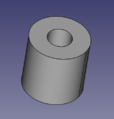
Fig. 2: Growbot Motor Mount Standoff.
-
Fig. 3: Growbot battery mounting unit.
-
Fig. 4: Growbot E-Stop mounted on top of bot.
-
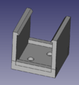
Fig. 5: Growbot E-Stop automotive relay holder.
-
Fig. 6: Wiring Diagram for Growbot.
| Part | Files | |
|---|---|---|
| Motor Mounting Brackets V3 | FCStd | STL |
| Motor Mount Standoff | FCStd | STL |
| Battery Mount V2 | FCStd | STL |
| Temporary E-Stop Holder | FCStd | STL |
| Relay Holder V2 | FCStd | STL |
| Wiring Diagram | ||
Semester 4 Fall 2020: Senior Capstone[edit | edit source]
Growbot[edit | edit source]
This semester I was the project lead as well as the hardware lead for the OSHE Growbot Project. I organized the team to get achieve our goals this semester despite COVID-19 delaying some of our initial plans.
I have been able to accomplish a lot for the charging circuitry on both the base and the bot itself as working to get the bot moving. I started by reorganizing the electronics on board the Growbot to a more condensed layout in order to accommodate the battery management system that had to be installed. The battery management system monitors the voltage across each of the cells of the LiPo battery in order o avoid destroying the battery. The next step was to install circuitry to handle the power delivery to the battery management system. This is done by supplying the bot with 12VDC from the power supply unit mounted on the charging station. The battery management system is powered by the 12VDC and will charge the battery at a safe voltage after the user hits the "start" button. While the rest of the internal circuit could not be installed, the plans are laid out and the parts ordered. The 12VDC power coming into the bot will also go to a 5V regulator that will be used to power the raspberry pi and some of the sensors while the bot is being charged. The bot is currently set up to operate using mechanical switches which will be replaced with relays once the programming is completed.
The base (charging) station consists of the 12VDC power supply, an electronics enclosure, and the wire following circuit. The PSU supplies the electronics enclosure which contains 2 mechanical switches (to be later replaced with relays) with one going to the wire following circuit board and the other going to the bot. Right now, the bot must be connected to the base station with human intervention but eventually this process will take place using prongs on both the bot and the base that will touch as the bot runs into the base's prongs. For the base, I designed the electronics enclosure as well as wired up all of the switches and wire following circuit board. The wire following circuit board is mounted in the electronics enclosure and the wires are twisted together and ran down the side of the base until they meet the path of the bot in which they travel in opposite directions to form a circle. The twisting of the wires causes the bot not to sense the wires since the fields of the two wires are equal in magnitude and opposite in polarity, effectively cancelling one another out.
-
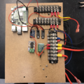
Fig. 1: Growbot electronics new layout.
-
Fig. 2: Growbot electronics new layout.
-
Fig. 3: Growbot charging base.
-
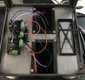
Fig. 4: Growbot charging base switch enclosure.
-
Fig. 5: Wiring Diagram for Growbot Charging Base.
| Part | Files | |
|---|---|---|
| Electronics Enclosure | OpenSCAD | STL |
| Base Wiring Diagram | ||
Open Source 3-D Printing Class[edit | edit source]
Mini Projects
-
A picture of my operational 3-D printer
-
3D Printing Failure Database, Ghosting with 4Runner Keychainl
Big Projects


